Announcement

Collapse
No announcement yet.

My Asymmetric Electrodynamic Machines

Collapse
X
 
  • Filter
  • Time
  • Show
Clear All
new posts

  • Cornboy is right...

    Originally posted by machinealive View Post
    Hey UFO,

    I think the imperial rotor would be too small, to use as the inner stator, for the Figuera gen. Here is pic of an aluminum tube the same size as the imperial housing.


    The big stator poles are laminated. I'm gonna get it sandblasted and painted, John Deere green .

    Maybe, for the Figuera gen, I'll build the inner stator with oak.
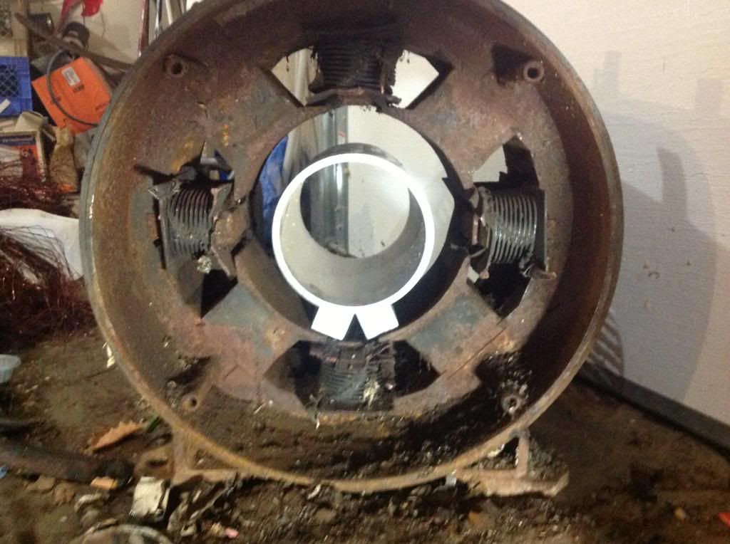
. Just 4 poles to match outer stator.

    @Dana, if I only knew how to help you, except to get my driver setup going. Thank you for your effort, you're doing a great job.
    Hello Friend,

    Cornboy is right...the Inner Exciters core MUST BE made out of steel...and equal/same Area of front of Poles to the outers, as center cores volume (where you wrap the coils)...otherwise the HOT Magnetic Fields/Flux will be uneven...therefore, not good Induction/Output. Remember we are dealing here with Hot, not Radiant...


    Regards


    Ufopolitics
    Principles for the Development of a Complete Mind: Study the science of art. Study the art of science. Develop your senses- especially learn how to see. Realize that everything connects to everything else.― Leonardo da Vinci

    Comment


    • Exciting.

      Originally posted by Ufopolitics View Post
      Cornboy,

      Dreams become reality my friend, you know that...

      My "Dream" was not related to Energy (it just "came" to me...like I have posted before)...but to build a very stable, flying craft...that would NOT resemble ANY of the existing ones... so far...in our entire history...all this...was "once"... just a dream...

      I believe Humanity needs to "brake frontiers"...first, "locally" ...then..."Globally" or flying freely...between our own planet...

      Airport$ Custom$...Toll$...Street$, Highway$, Expre$$way$...Limitation$ would be COMPLETELY destroyed...gone...history...

      We need that in order to reach Higher Civilization Levels...as much as we need Free Energy Devices.

      As it ALSO would have to be "Open Sourced"...as you will understand it is "also" a "National Security Treat"...

      Imagine you could "Fly" your Load of Garlic ANYWHERE...and ANY Weight you Want...

      Possible?

      Yes, and being as serious, as a Heart Attack.

      I will eventually display to you all the "Counterweights Engine Design"...however, I see it like the making/constructing/training of another "Super Heavier Weight Fighter"...for a "Fight" that is about to be finished very soon...my friend...hope you understand what I mean.


      Regards


      Ufopolitics


      Thanks UFO, i am not quite sure what you mean, but i eagerly await, your new designs, as you probably know by now, i like to plan ahead, with building from scratch,it can take some time to get quotes etc.

      I need to do some modification to the commutators of the MAG3, and that finishes all the structual embodiment work, ready to finish the epoxy build up removal, from the rotor, and then wind the rotor.

      After that, it's wind the stators, and i will draw some alternatives and post them for your advice, before i start them, if you don't mind.

      Lots a work, but Exciting as well.

      Warm Regards Cornboy.

      Comment


      • Dana,

        There is no overlap in the program that I posted. If you examine it you will see that in the time period that each led is on or each pin is active that the value for the duty cycle is incremented up or down by 5 points each time it goes through the loop. The effect this has on the leds is that they will get brighter until they reach the maximum brightness and then they will dim until they do not have enough voltage to light up. After the wait period at which they exhibit a duty cycle of 0 to 255 in other words nothing to 100%, they are shut off on the line analogWrite(blueLED, 0); thus they do not conflict with each other. This pin is off while the other three are operating. But while the pin is on the pulse wave can have a different intensity based on the setting of 0 to 255. This is why the leds get brighter as the numbers grow larger. You need to separate in your mind the duty cycle frequency from the frequency of the machine. The frequency of the machine has 4 on periods in every rotation. Within that on period the frequency of the duty cycle can vary from 0 to 255 giving a much stronger response or weaker response if necessary to back off the rpms. Look Dana I respect everything you are doing and I love the work being done on these two threads. I have built two replications and am working on my third. I only recently purchase the Arduinos that I have. So I am by no means an expert on all the things that the arduino can do. I know that all of the programming for the Arduino comes from C++ language. That I am well versed in. I have gone through many tutorials on line as I imagine you have also. I believe knowledge is power, but only if the foundation is correct. I certainly don't mean to insult any one or be derogatory. I know everyone here is making honest efforts to find the truth, and I believe we will.

        Cheers,

        Garry

        Comment


        • Misunderstandings...and Solutions.

          Originally posted by prochiro View Post
          Hi Garry

          I guess I do not understand you can have more than 25 percent duty. The total possible is 100, divided into four parts which is 25 percent each and UFO's requirement of no overlap so Amps stay down. If at any time there is an actual condition where any two of the four are on at the same time, Amps go high as well as spikes back. The only case where I could see that an overlap would be maybe useful is for higher power transfer for boosting but this has a vary high cost at input.
          However, if an overlap was desired for boosting, do you know of an easy way to do this without a lot of fractionating of high and low timing?
          I would like to have ideas and help. Maybe you could write a quick outline of how you would do this and then we have even more choices.
          My outline is more or less what I described in the above post. I am still not settled upon fastest and safest method to tx rx. I2C is unsafe even when adding caps( it only takes and stop to crash). I have not tried the latest more expensive accessories yet but the cheap ones are slow and junk. What would you use.
          Dana

          Dana,

          There is no overlap in the program that I posted. If you examine it you will see that in the time period that each led is on or each pin is active that the value for the duty cycle is incremented up or down by 5 points each time it goes through the loop. The effect this has on the leds is that they will get brighter until they reach the maximum brightness and then they will dim until they do not have enough voltage to light up. After the wait period at which they exhibit a duty cycle of 0 to 255 in other words nothing to 100%, they are shut off on the line analogWrite(blueLED, 0); thus they do not conflict with each other. This pin is off while the other three are operating. But while the pin is on the pulse wave can have a different intensity based on the setting of 0 to 255. This is why the leds get brighter as the numbers grow larger. You need to separate in your mind the duty cycle frequency from the frequency of the machine. The frequency of the machine has 4 on periods in every rotation. Within that on period the frequency of the duty cycle can vary from 0 to 255 giving a much stronger response or weaker response if necessary to back off the rpms. Look Dana I respect everything you are doing and I love the work being done on these two threads. I have built two replications and am working on my third. I only recently purchase the Arduinos that I have. So I am by no means an expert on all the things that the arduino can do. I know that all of the programming for the Arduino comes from C++ language. That I am well versed in. I have gone through many tutorials on line as I imagine you have also. I believe knowledge is power, but only if the foundation is correct. I certainly don't mean to insult any one or be derogatory. I know everyone here is making honest efforts to find the truth, and I believe we will.

          Cheers,

          Garry
          Hello and Welcome Garry!

          We really appreciate someone like you contributing here on the Programming Codes, as also on Controllers Data.

          For sure We will be open for new Input/Opinions Contributions!

          Now, related to Quad Signals for Asymmetrical Controllers...some things you must realize:

          1-We are using Arduino to Emit ONE SAME Signal, but spread through Time and "Mirrored" into Four. (We could do it on Two, or Six...but for Imperial is Four (4))
          2- What can NOT overlap is the On Times between "mirrored" Gate Signals.

          Hello Dana!

          I believe I know where some of this misunderstanding could be...

          Dana, in your post above, you are completely right, and I do NOT want Individual Channels signals to Overlap through Time...BUT, relating strictly to On Times.

          However, I believe it is my fault, because I have displayed the Graphics to this Signals in a LINEAR FASHION , like on Diagram on bottom left:

          [IMG][/IMG]

          And of course, that is exactly the way that an Oscilloscope would display them on a Two Dimension (Time X Signal Width/Height) on a Flat Line screen...Then Your Calculations on dividing the Duty Cycle (Based on "Time On") in Four (Four Gates/Four Channels) will result in NO MORE than 25% Duty per Signal.

          However, if you look at the Way they manifest/enter at Machine's Gates...then notice it is quite different.

          At Machine they enter in a Radial/Curved Input, not Linear, therefore, here it is based on Angles of Duration, and NOT on straight/linear divisions.

          Since We are "Injecting" Signal on the outer perimeter related to the Commutator at contact with respective Four Brushes...then We could have more than just 25% of duty cycle there.

          Let me see if I could explain better:

          Four Brushes/Gates are exactly located every 90º APART from each others. Therefore, even if you see on Scope they are "almost" overlapping ...in reality, at Machine they are NOT...

          At Machine the Time is "Curved" not Linear, related to Signals Input, therefore, this curvature "stretches" time, allowing more percentage of Duty Cycle than 25%.

          Look at Diagram below:

          [IMG][/IMG]


          Now, compare the two Dimensions shown by Arrows, Curved and Linear...which one is longer in Time?

          Also Dana...remember We are using the SAME SIGNAL...for example in the Linear Diagram I have shown above...I am displaying approximately a 50% Duty for that Signal...and still they do not overlap/Intersect their times on. When you increase duty...remember they will "stretch" but EVENLY towards rotation sense (forward)...so still will not overlap unless is at 100%...

          What does get "fractionated" here... in approx 1/4 , is our Amperage...

          I hope this explanation would "clear" any misunderstandings...

          It would be simple to verify this for you Dana...since you have the complete Set Up already running perfectly.

          Get the Signals to go above "Your Linear" 25% On...and check if amperage will rise...keep doing it until there is amp increase ...then look at your Scope Signals...'


          Actually, what does NOT ALLOWS for Signals to EVER Overlap, is the Established Dead/Off Times between them (and by the way, Off Times are ALSO the SAME Time amount for all Channels)..when Off Times between signals equals Zero, then, they start overlapping from there on...

          My BIG question is:

          Can we Adjust the Off/Dead Times Duration (And I am NOT referring to the Off Times at Signal)Independently from Duty/Frequency on Signal, just producing it as a "Delay-Duration Time Parameter" to "trigger" next signal?

          If We could achieve this...then, this parameter would be the Main Speed/Torque Controller....Duty Cycle could be whatever percentage...and still...amperage would reduce like so far Dana have achieved and maybe more than that.


          Regards


          Ufopolitics
          Last edited by Ufopolitics; 07-03-2013, 08:40 AM.
          Principles for the Development of a Complete Mind: Study the science of art. Study the art of science. Develop your senses- especially learn how to see. Realize that everything connects to everything else.― Leonardo da Vinci

          Comment


          • Imperial Motor came!

            Hello All!

            I'm glad to see that everyone is in Good Spirits and the Team bond is growing stronger.

            My motor came today! I'm so excited. I want to open the box right now but I have to wait. My place is one open room style. I have small children and they get into everything and anything!!! I have to wait for the motorcycle shop to clear a space for me, our motor and my bike.

            I showed the shop Engineers the pics and vids of the Imperial running.(good job Dana). The shop owner call the boss of Mugen directly on his personal phone immediately! Mugen is the company that made the electric racing motorcycle, The Shinden Ni, for Honda. They talked for 20 minutes about the Imperial's 2 commutators and the Amps dropping to the floor. After the shop owner got off the phone, he said, "Lets build it." I went from having to wait until the end of August to get space, to this month!

            Thank you UFO and guys! I will try my best

            Keep it Clean and Green
            Richie

            Comment


            • Cornboy,

              Every time you mention garlic I wonder if you are from Gilroy, which is only 30 minutes from me.

              Dave
              “Advances are made by answering questions. Discoveries are made by questioning answers.”
              —Bernhard Haisch, Astrophysicist

              Comment


              • analogWrite

                Hi Garry
                I an really trying hard to see how the analogWrite() could be utilized but still see that it can not be used as it forces a frequency of 490. This is way beyond the 30 Hz the Imperial is comfortable at. If I raise the Hz to 32, she drags down as also at 26Hz. Also at higher Hz, we have to deal with more backfire which is what Machine ran into. I will continue to work to understand this better yet with maybe a setup on the Imperial this weekend and let her decide of she likes it or not. Thanks Garry
                Dana
                "Today's scientist have substituted mathematics for experiments and they wander off through equation after equation and eventually build a structure which has no relation to reality."
                Nikola Tesla

                Comment


                • This tutorial explains the way the Arduino pwm works far better than I can.

                  Arduino - PWM

                  You are almost there UFOPolitics. But because the Arduino operates at 500 hz and the pwm signal is the inverse of Arduino the time period may have many square wave signals in a given time period. This breaks down to a cycle every 2 milliseconds. Well I have work to do and this discussion has been beat to death.

                  Cheers,

                  Garry

                  Comment


                  • Hi friends,
                    back again from vacation and trying to catch up the stuff. Unfortunately the health of my wife is getting worse - hence less time left :-) for free energy.
                    I am so sorry you experience smoking FETs. Feel free to ask questions. I want you to solve your problems!
                    JS
                    Experts spend hours a day in order to question their doing while others stopped thinking feeling they were professionals.

                    Comment


                    • UFO

                      I got my parts today, so hopefully, I'll get at the drivers this week. I'll post on the other thread, until I get something working.

                      UFO or Cornboy

                      This is the last time I'll post here, about the Figuera generator, unless you want me to post here, but I have couple questions. So, I have a big 4 pole for outer stator. We are not sure how big of space we can allow for middle rotor, which we can spin or not, but I will spin, the dynamic version. Cornboy you mentioned 15 mm maybe. Then we have our inner coils.
                      Now my questions,
                      1. The inner coils are also stationary, or do they spin with middle section(rotor)? I thought they were stationary, and only middle section spins.
                      2. How many coils should the rotor have,middle section.
                      3. If I make the same 4 poles for inner section, with exact same size coils that is in the outer stator, what should the length of middle coils be, 1:1/4 with 4 x diameter of stator coils?

                      The stator coils will be huge, maybe we could go 2-3" for air gap.

                      Johnstone

                      Hope you had a nice trip, glad you're back. If my drivers still don't work, I'm going to make a vid of the drivers switching lamps, with scope at gate, and source and drain, maybe you could analyze. I don't want to bug Dana, as he is already very busy. I re-did the grounds, lets see what she'll do.

                      Machine

                      Comment


                      • Hi Garry,
                        welcome as contributor!

                        FYI: My coding experience ended long ago but I often discuss with SW engineers the architecture of new programming approaches - hence I am no redneck in these matters.

                        I'd like to add a suggestion and ask you for your vote.

                        I studied Arduino properties intensively and vote that there is no elegant and easy way to use PWM functions in order to get precise signals - UFO type.

                        The reqirements are:
                        • variable frequency,
                        • variable duty cycle,
                        • scalable 4/6 phase signals,
                        • low processor load,
                        • precise timing.


                        My notions:
                        • In order to face those requirements I feel we need to leave those predefined functions like PWM.
                        • Pulse generation is time critical - all other functions NOT.


                        Pulse generation step 1 - timing:
                        What about using an array.
                        • For 4 phases we need 8 values each representing the high time and low time of each phase signal (12 values for 6 phase - dedicated to MAG3 in AU/Cornboy).
                        • On initialisation the timer will be loaded with the first value (16 bit timer if you decide to).
                        • On timer expiration it generates a high level interrupt. Within the Interrupt routine the timer will be relodaed with the next value out of the array.
                        • At end of array it will reset the pointer to the beginning of the array.
                        • There is absolutely no drawback if we use 4 or 6 phases.
                        • Thus we get a predefined and very pricise but still variable heart beat.
                        • The timer vaues will be calculated and modified by a low prority function. I admit the calculation of array values is a certain effort - but does not affect real time pulse generatrion.


                        Pulse generation step 2 - output ports
                        • The patterns for output ports will be stored in the array as well. We extend the array by adding after any timer value a bitmap for output ports (byte)
                        • At any timer interrupt the next pattern will be output to the corresponding port (byte).
                        • There is absolutely no drawback if we use 4 or 6 phases (we can extend to 8!)
                        • The output patterns are fixed values and will never be changed.


                        Pulse generation step 3 - enhancements
                        • If we are short on port pins we can add an additional mask value into the array. A simple bool calcualtion will read the port values, mask the phase pins out and add by OR function the intended 4 or 6 bit pattern.
                        • Alternatively those bits of the byte being not phase pins can be used as inputs. In thiscase we do not need any masking.


                        Value change /frequency / duty cycle
                        As I mentioned above the change of values is not critical in time. Hence the change can be calculated for new timer values and stored in the array. The calculation routine can be lowest priority level.
                        There is essential to synchronise value changes with interrupt routine in order to prevent transient and unsolicited port jam. I imagine to use 2 arrays and swap the pointers after value any change anly - controlled / synchronized in the interrupt routine

                        Governor
                        There is an official PID governer library available for Arduino. I studied the implications coverd and detected that the major code is for delaying with faults and exceptions - some problems I never heared before. Hence: Using this lib could be a direct and genuine approach with less head ash.
                        For first steps the I and D component can be canceled completely in order not jump in deep and troubled waters with initial control of the setup.
                        I am quite sure the phase control and governor function can be performed with one single Arduino!

                        Data transfer
                        I strongly vote to implement a serial / USB link to PC or other Ardunino in order to prevent the pulse generator from overload.
                        BTW: For convenience Arduino can be equipped with BlueTooth / COM I/F (spend some few bucks at eBay) in order to prevent any direct electric connection to PC or other Arduino.

                        My program attempt
                        Some month ago I wrote a program for pulse generation like mentioned above but experienced some flaws with serial link and pointer control. I am not able to debug it by myself.
                        There is control from PC for frequency and duty cycle in that program.
                        On request I can forward my Arduino program but beware! it is horrible coding style. It was mixed up of different Arduino examples.


                        Dashboard
                        Dashboarding is a special implication and can easily be done by a PC including storing of Data to charts and files, calculationg and displaying any form of gauges. Good news: There is no PC programming required. I own i.e. the program ProfilabExpert Consult the link in order to see the wonderful dashboards (scroll down). It runs with Ardunio as well and I got it running in my lab. Within minutes any individual dashboard will be available.
                        Once you have a running serial link I would be willing to supply a dashboard for PC on request.

                        The facts above would be my plot and suggestion for controlling UFO setups. It was tuned for lowest processor load and optimize scalability.
                        Feel free to discuss, adopt or discard

                        rgds JS
                        Last edited by JohnStone; 07-03-2013, 09:19 PM.
                        Experts spend hours a day in order to question their doing while others stopped thinking feeling they were professionals.

                        Comment


                        • Originally posted by machinealive View Post
                          ...
                          Johnstone

                          Hope you had a nice trip, glad you're back. If my drivers still don't work, I'm going to make a vid of the drivers switching lamps, with scope at gate, and source and drain, maybe you could analyze. I don't want to bug Dana, as he is already very busy. I re-did the grounds, lets see what she'll do.

                          Machine
                          Thanks - exciting trip!!

                          You are welcome!

                          If lamp switching is OK then next step should be connecting motor windings and bulbs in series for test purpose. No direct jump in troubled waters!
                          JS
                          Experts spend hours a day in order to question their doing while others stopped thinking feeling they were professionals.

                          Comment


                          • Underneath.

                            Originally posted by Turion View Post
                            Cornboy,

                            Every time you mention garlic I wonder if you are from Gilroy, which is only 30 minutes from me.

                            Dave

                            Hello Dave, if you mean Gilroy California, no, i live down under, or if the poles swap, then up above Ya.

                            I live on almost the same latitude as UFO, in the beautiful Byron Bay hinterland on east coast of Australia.

                            I have a 90 acre mixed Bio-Dynamic farm, that i make a living from, and speaking of Garlic, i will have to plant an extra couple of rows every year, to keep building UFO designed motors, until i reach my goal of a heavy duty traction motor suitable for all kinds of EV applications.

                            Please keep us informed of your quest to replace your battery pack in your electric Polaris Ranger, Dave.

                            Warm Regards Cornboy.

                            Comment


                            • Welcome JS.

                              Welcome back John Stone, great to have your input here again friend.

                              Sorry to here about your wife, i wish you all the very best of luck.

                              Warmest Regards Cornboy.

                              Comment


                              • Figurea.

                                Originally posted by machinealive View Post
                                UFO

                                I got my parts today, so hopefully, I'll get at the drivers this week. I'll post on the other thread, until I get something working.

                                UFO or Cornboy

                                This is the last time I'll post here, about the Figuera generator, unless you want me to post here, but I have couple questions. So, I have a big 4 pole for outer stator. We are not sure how big of space we can allow for middle rotor, which we can spin or not, but I will spin, the dynamic version. Cornboy you mentioned 15 mm maybe. Then we have our inner coils.
                                Now my questions,
                                1. The inner coils are also stationary, or do they spin with middle section(rotor)? I thought they were stationary, and only middle section spins.
                                2. How many coils should the rotor have,middle section.
                                3. If I make the same 4 poles for inner section, with exact same size coils that is in the outer stator, what should the length of middle coils be, 1:1/4 with 4 x diameter of stator coils?

                                The stator coils will be huge, maybe we could go 2-3" for air gap.

                                Johnstone

                                Hope you had a nice trip, glad you're back. If my drivers still don't work, I'm going to make a vid of the drivers switching lamps, with scope at gate, and source and drain, maybe you could analyze. I don't want to bug Dana, as he is already very busy. I re-did the grounds, lets see what she'll do.

                                Machine


                                Hello Machine, with the figura generator, it is probably best to post on the Reinventing the wheel thread, that way we can keep the progress compact, for others to follow.

                                If you look on that thread UFO posted a drawing for me to help me understand a possible setup. The Internal and external Exciters are stationary, and with as small an airgap as possible, we need to spin a non metalic drum holding the Excited wiring, which needs to be multy phased, wave wound like in a auto altenator, for the least possible Drag.

                                These stationary exciters could be pulsed with same signal as pulsed stators, on imperial, with wound stator fields, the resulting outflow from the multi phase rotating drum windings/gen could be then rectified and regulated for battry charging the prime batteries or another bank with a battry swapper.

                                Hope this helps, if not keep asking Machine.

                                Warm Regards, Cornboy.

                                Comment

                                Working...
                                X