 Tweet
Tweet
researching a bigger operation
Hi Ufo,
Found a 3kva Mecce Alte, 2001. Not supposed to be over used. I know how you raved about the brushless design on you 2010 model. Not as much wattage. Do you think the design of their earlier models will be as efficient? And no prob on finding coupling mechanisms?
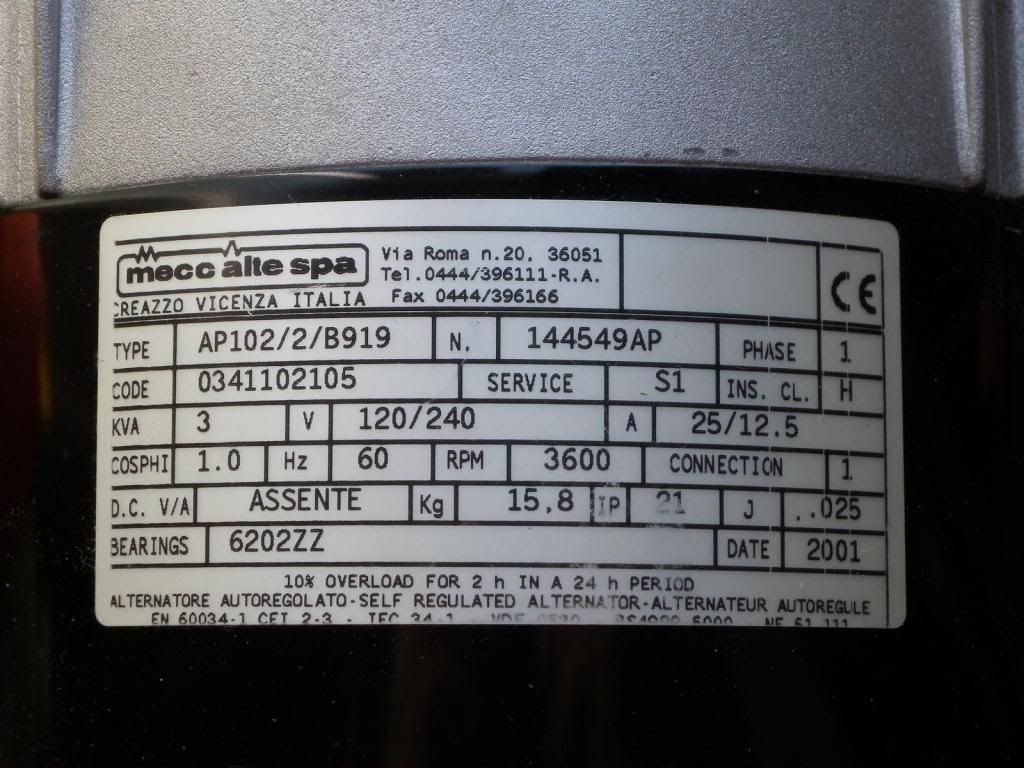
thanks again.
Joe
Hi Ufo,
Found a 3kva Mecce Alte, 2001. Not supposed to be over used. I know how you raved about the brushless design on you 2010 model. Not as much wattage. Do you think the design of their earlier models will be as efficient? And no prob on finding coupling mechanisms?
thanks again.
Joe


")


Comment