Announcement

Collapse
No announcement yet.

My Asymmetric Electrodynamic Machines

Collapse
X
 
  • Filter
  • Time
  • Show
Clear All
new posts

  • Hello folks

    Finally have a chance to write more.

    @ Machine, You better believe that by pulsing WILL reduce draw...and still be able to withstand Generator demand...way different than linear feed my friend!
    Good. Previous I ran motor/gen with 48v constant dc, rpm about 4100, 1000 watts lowered rpm to 3600. So then I was hoping 72v constant dc would run the setup at 6000 rpm, still 500 rpm/1000watts out. Unfortunately, 72v constant dc only did 5000 rpm, @ 72 amp input. 1000 watts one side lowered rpm by 500, input amps was at 70. Other side 1000 watts lowered rpm by 500, input amps was at 69, it was getting quite warm. I stopped testing. But still 500 rpm/1000watts out.

    So, if we can get the rpm to 6500 at less then 72 vin, at less then 69 amps in, with gen unloaded, I won't have to buy more batteries., and we will know its beat, before we load gen.
    I was also only using p1 and p15 in parallel. p8 and p22 fed caps (20 volts held constant, while running home made 5 pole). Dana has shown us how low the amps are going to be when pulsing.

    Are You using the FET's as per JS Monster spec's?
    Yes, and they are less then 10 bucks at digikey now, I thought they were 20 bucks before. I shorted out my heat sink to a power pin. I only lost one fet though. It's running now, running good. It's all set up on motor to start testing at 12v, I won't be free till Friday to sit down and test. I'm very excited to try this setup.

    @Koggs
    Hello Koggs. You are right that coils will get larger, as spiral get bigger and that will unbalance rotor. But that is as per UFO's guidelines. More Asymmetry.

    @ Lightworker
    Hey Lightworker
    I've been catching up on posts. Thank you Light, You have been doing a lot of work, Its going to be very helpful. Have a good night, I'm crashing too.

    Machine

    Comment


    • Thrashing.

      God i feel guilty, going to sleep way earlier than you guys, Light, DANA, Machine, Hitby, ect, it's just habit, i get up at first light, before dawn 7 days, that's farming.

      @ Hitby and KOGS, i am sure that the winding method is " Spiral of LIFE ", ending up like a VORTEX, spiral.

      Sure, out of balance as we have been taught, and i can just picture the hammering effect UFO speaks of, also coupled with the increasing magnetic pattern as the spiral gets closer to stators, all adding to a thorough thrashing of the rotor, every revolution.( POOR ROTOR ), good for us though.

      @ Machine, can't wait for your pulse testing, good work.

      All The Best, Cornboy.

      @ DANA, the noise of you silently working away is very Loud.


      @ Light, thanks for your electronic knowledge here, you and DANA are really getting it together, to benefit the electronically challenged, like ME.
      Last edited by Cornboy 555; 05-30-2013, 07:50 AM.

      Comment


      • Machinealive you fried your fet(s). Question?

        Back in March UFO had connected a liquid solenoid to his motor. Wouldn't a liquid solenoid protect our board and fets!? It would be like a first line of defense and the fets would be the last line defense to protect our system from heat?

        Keep it Clean and Green
        Richie

        Comment


        • Originally posted by prochiro View Post
          ....
          The hall sensor has a reputation of giving a wave rather than a true on/off....
          Hi Dana,
          that's only half of the coin - fortunately!
          Basically the hall effect is of analog nature as you mentioned above. But we are blessed nowadays with cheap integrated circuits and - good news - your/our problem had been solved.
          Example:
          https://www.sparkfun.com/products/9312
          data sheet
          Will do well up to 10Khz
          Besides a schmitt trigger circuit it contains a latch circuit. Hence the output leveel will be sustained up to the moment a reverse magnetic flux triggers the internal latch. That eliminates any danger of bouncing and gives a signal suitable for direct feed to arduino.

          See diagrams/comments 13.x and 14 in datasheet
          - Please use a pull up resistor 1K..10K as the output is of open drain type -> can sink current only. You may want to add a LED in series to resistor in order to see it functioning.
          - Use a cap 4.7nF for preventing noise from environment.
          - Twist all 3 wires (VCC/GND/OUT) between sensor and Arduino on order to prevent any crosstalk from environment
          - Use a bypass cap 100nF at VCC/GND

          There are plenty of other ICs available. If you are in doubt if your source is applicable please ask!
          JS
          Experts spend hours a day in order to question their doing while others stopped thinking feeling they were professionals.

          Comment


          • Hello Kogs, Good Morn All

            Originally posted by Hitby13kw View Post

            As to your other questions, my thoughts follow however (remember I’m rewinding my motor a third time now because of going off on my own path) so UFO we both need your insight.

            It is my understanding that by winding the Imperial in the pair sequence 1,2,3, . . . to 28 we end up with the Spyro_of_Time type of design (see page 112 post 3335), if you did a pair sequence of 1,15,2,16,3,17, . . . to 14,28 it would be more of a ying yang pattern (my guess is it would turn) but might not reach as high RPM under load – it is on my list of things to try (so many things to vary – so little time)

            Originally posted by IanKoglin
            G'day Hitby13kw,UFO
            What I mean to say is to wind each pair of coils and connecting them to the commutator as per UFO's diagram for winding but winding each opposing pair to keep the weight as even as possible making sure they are wired to the correct pos on the commutator it should fire up the right coil in the correct sequence its just IMHO that as you wind the armature in series like in p1 ,p2, p3 etc would not the windings gradually get larger because of the extra diam as they are wound over the other windings

            Kindest Regards

            Just trying to get my head around things

            Hello Kogs, Hello Hitby13kw, Hello to All,


            Someone already ask me this question, in a now "pretty old" post...about winding Pairs corresponding at the opposed 180º, like P1/P15, then P2/P16 and so on...and the reason why NOT to do it this way is not only related to the electromagnetic interactions, but, to understand that the rotor must develop a full revolution cycle of 360º from minus to plus...in both...magnetic interactions AND Coils Mass Weight, that creates the Physical Unbalance we need to propel to great speeds once we brake the inertia forces...developing a more robust machine.

            If we look at P1 then to P28 (last Pair at Imperial) when doing it in a sequential order (1,2,3,4...15...28)...we will notice the huge difference between P1 and P28...and that is not only looking at those two Pairs but at the other coils underneath...

            If We balance our Coils-Pairs, every 180º...then We do NOT get the full Revolution Cycle of 360º,but at 180º...and yes...there will not be the "Asymmetric Spiral", and no "Hammering Effect" either...as this will create a "Braking Effect" on the long run.

            Now, when we pulse this Sequential order through Arduino/Monster Pulser...That light moving (yes, single light moving from LED 1 to LED 4) we see from Gate One(1) to Gate Four(4)...will be in charge to maintain those cycles spinning precisely...and at higher speeds they will balance up.


            Hope this answers your questions/doubts Kogs...


            Warm Regards


            Ufopolitics
            Principles for the Development of a Complete Mind: Study the science of art. Study the art of science. Develop your senses- especially learn how to see. Realize that everything connects to everything else.― Leonardo da Vinci

            Comment


            • Hello JohnStone
              Thanks for the post. I am on the same track. I ordered some arduino sensors from Electrodragon (SKU 7000014) to test. They are 3144 hall switch based with a LM393 to boost and have several resistors and I believe caps on board. If they work like they should, code should be simple but by trial and error development.
              Dana
              "Today's scientist have substituted mathematics for experiments and they wander off through equation after equation and eventually build a structure which has no relation to reality."
              Nikola Tesla

              Comment


              • Related Speed Sensing from an Asymmetrical Machine...

                Hello to All,

                I see you guys are concerned about being able to read speed as accurate as possible from your Imperial-Generator Head Common shaft...as I see that Hall Sensors/Magnets and other ways will not be as accurate as well...

                May I suggest a "mechanical" and simple idea?

                Asymmetrical Machines design provides independently energized Pairs/Coils per One Single Gate ...and If Your windings are correctly built...Not One Coil should be grounded to Rotor Steel Mass...or it would be incorrect...

                So, then...could we just ground one end of just One Pair in the whole 28 Pairs...say P28...then read from Motor Ground and just Any One Gate at the same end where Pair 28 was grounded (Preferably a Negative Side Gate)...and we will be getting a "closing switch" there... every time P28 grounded Commutator Element, passes through that particular gate, and of course those two terminals (ground and gate) would have to be rectified through diodes not to get reversed currents...or High Spikes...or the Negative Channel feed from FET's.


                That switching "On" should occur at every Full and Accurate Revolution...

                The only problem I see so far...would be interference with Generator Frame Ground...that is a "must be done"...and Prime Mover Ground...

                On the other hand, I believe it should work without interfering with P28 normal operation/duties...but again, I maybe wrong or overlooking at some possible crashing here...you guys let me know what you think...it is just a simple idea to be tested.


                Regards to all


                Ufopolitics
                Last edited by Ufopolitics; 05-30-2013, 12:58 PM.
                Principles for the Development of a Complete Mind: Study the science of art. Study the art of science. Develop your senses- especially learn how to see. Realize that everything connects to everything else.― Leonardo da Vinci

                Comment


                • @midaztouch
                  The mercury switch was to replace the fets, not protect them, as they couldn't stand the current spikes. But the mercury switch wouldn't switch at a high enough speed to be usefull here, I found, I think Dana and UFO would agree.

                  I was using the mercury switch as safety with constant dc. I tried to run motor at 72 v and melted the light switch closed. I shut it off by knocking diodes off with broom handle. I was very lucky the diodes were there. So then I put the Hg switch back on.

                  I won't be testing this setup with the mercury switch, at least until the current starts going up. Hopefully we won't need it again.

                  Machine

                  Comment


                  • @machine

                    Do you have a vid for the last test? Why did you use straight dc for testing? What was the Hz when you had to shut her down?

                    From what I gathered from Dana's tests, @72volts and 60hz using the pulser, your amp draw should be under 15 amps. That would coincide with Dana's previous tests.

                    Try this, use the pulser @72v and go past 60hz unloaded. The last test you used 36 volt at 227 hz. The motor achieved over 9000 RPM's! Please use extreme caution my friend. Like duck down or create a shield and turn up the hz really high for a few seconds. Video it but hide! If there is an accident, you can get a new camera but not a new you. I want to see if the fets can handle the stress better @72 volts when being pulsed. If your up to it.

                    Keep it Clean and Green
                    Richie

                    Comment


                    • MachineAlive, What the heck is going on over there. Broom handles and melting witches? Oh, you said switches, my bad... You do have something, if you were pulsing, shorted thru. That still sound vary high for straight linear. Please be careful, your one of the last real crazy workers we have. Do a quick continuity test at slow pulse of the fets by no power from battery or motor but test the two legs while pulser is running and hear the beep, beep, beep on all fets, that still does not mean one is gone as it takes both pair to show bad that way. Also what is getting hot, look into that. Fets don't get over 80 degrees at 60 volts. Are your wires longer than suggested or smaller. Check it out and PM me if you want to go over things step by step. You got guts man,,,,,,72 Amps,,,.
                      Dana
                      "Today's scientist have substituted mathematics for experiments and they wander off through equation after equation and eventually build a structure which has no relation to reality."
                      Nikola Tesla

                      Comment


                      • @UFO:
                        Your suggestion for rpm sensing is well funded and should be followed for optimizing later on. To interpret such a noisy signal might be a task for itself and will not aid for finding sweet spots easy. Hence for first lab tests a hall sensor shall be preferred in order to separate power and sensing worlds properly.
                        Nevertheless I will keep your suggestion in mind

                        @ALL:
                        I feel it is essential to continue further tests with constant rpm and extend them in a scinetific reliable mannner. (not all scientific behaviour is faulty!).
                        Why?
                        Currently all parameteers are somehow variables and we will not get grip by juggling all of them at same time.
                        (A) As we know we want to have constant rpm and soon Arduino will control it - let's start with this firm anchor point. We need to hammer a fix pole into the ground in order to tie our variables to it.
                        (B) We need to cover the operating area with a net of measured points in order to get a rough overview on where we play in this game (get the biggest fish first with your net).

                        Input variables: load, voltage, frequency
                        Output variable: duty cycle, amp/power

                        I suggest the protocol below:
                        1.
                        Set: Constant voltage and constant load (i.e. 100W); rpm is fixed per definition and Arduino
                        Mod: Play with frequency for lowest duty cycle (set by arduino)
                        Note: duty cycle and input power or/and amperage Hence we have an idea on frequency sweet spot.
                        Net nodes(measurements) added: 1

                        2.+3.
                        Repeat like above but check for half and double frequency. Hence we know on how norow the sweet spot is.
                        Net nodes(measurements) added: 2

                        4.+5.+6.
                        Repeat 1. to 3. with 300W
                        Net nodes(measurements) added: 3

                        7.+8.+9.
                        Repeat 1. to 3. with 500W
                        Net nodes(measurements) added: 3

                        10.+11......+17.+18.
                        Repeat 1. to 9 with higher voltage
                        Net nodes(measurements) added: 9

                        19.+20.+.....26.+27.
                        Repeat 1. to 9 with even higher voltage
                        Net nodes(measurements) added: 9
                        ----------------------------
                        Total net nodes: 27

                        Hence you have a net of 27 nodes covering your operartion range estimated and we all can discuss publicly on where to continue focussing.
                        We might decide to:
                        • Draw some nice diagrams
                        • Extend the range of voltage, frequency, load
                        • Look closely inbetween some net nodes for finding the super sweet spot
                        • Perform same measurements after some mods of the motor, gen in order to compare
                        • .....


                        BTW: Ardunino might be programmed to find the very sweet spot for duty cycle and frequency. Further details on request.
                        JS
                        Last edited by JohnStone; 05-30-2013, 07:15 PM.
                        Experts spend hours a day in order to question their doing while others stopped thinking feeling they were professionals.

                        Comment


                        • Originally posted by iankoglin View Post
                          G'day Hitby13kw,UFO
                          When winding the 19AWG UFO said to wind one pair first then the opposite pair then run to test if OK then unwind and start winding in the series format as per UFO drawing.

                          Is it OK to wind first pair and then wind the other pair like above then wind each opposing pair and continue to test after each winding of opposing pairs in this way the armature would be proved OK at each level and probably be more balanced?
                          If not OK Is there a reason to wind in succession or series?

                          It's good to be part of this forum where everyone is interested in helping one another succeed no bickering etc.

                          I am determined to push ahead with my P56 motors else I will be left behind
                          I have already purchased an Arduino Nano it's on it's way but today I received this

                          Buy Processor & Microcontroller Development Kits Semi, Dev board, RX63N Gadget Renesas GR-SAKURA-FULL online from RS for next day delivery.

                          Perhaps it is cheaper if compatible

                          Kindest Regards

                          Running to keep up
                          Hello Ian, here is a comparison:


                          On the surface it looks like a vastly more powerful board.
                          I might personally want this one later on in my collection.

                          I need to look at much more in depth. It says:


                          (1) Rapid prototyping solution for embedded solution professionals, students and hobbyists who have no embedded programming experience.
                          (2) The cloud-based software development environment enables tablets and smart phones to be used as a user software development platform.
                          (3) Arduino compatible with superior performance and many advanced on-chip peripherals such as Ethernet and USB host.
                          (4) Promote user community site for users to ask questions and share knowhow and to announce event information.

                          Note: For information about Arduino, please refer to Arduino - Wikipedia, the free encyclopedia

                          Looks interesting but I do not know what type of learning curve it might require. Says user community support.
                          For now it might at a give away price but real price may be much more.
                          for example, at Element 14, at one place it says, "One person attending some course will be pick for a free RX63N

                          Good Luck

                          warmest regards

                          light

                          Wish all the best

                          Comment


                          • @ Dana...Broom handles and melting witches

                            Dana .....Broom handles and melting witches? Oh, you said switches, my bad.

                            That had to be the funniest joke so far! I couldn't stop laughing

                            Keep it Clean and Green
                            Richie

                            P.S. Am I correct in assuming that the amp draw be less than 15 if machinealive uses 72v pulsed?

                            Comment


                            • quad pent 10-pole update Grinding & winding

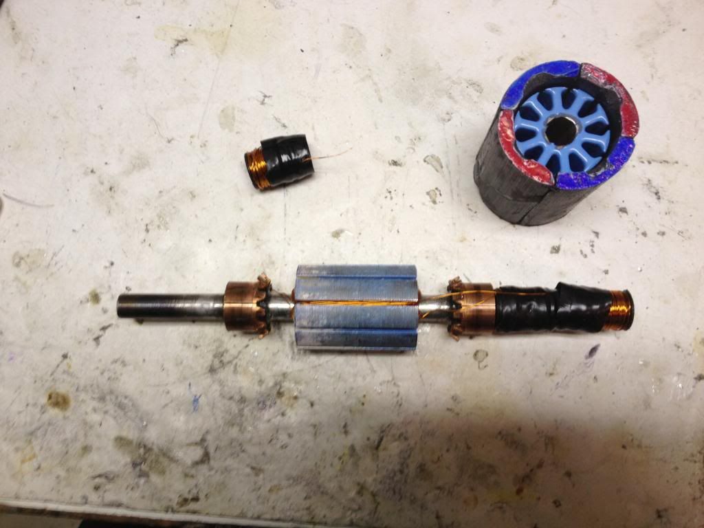
                              As I look into circuit manufacturers and BOMs, I am grinding & winding. Between making gen and motor and brush plates tunable and finding I had no rotational clearance in my motor body, mothers day, & memorial day, slow progress. But will definitely need this kind of a 4-stator motor figured out, how to wire and pulse it.

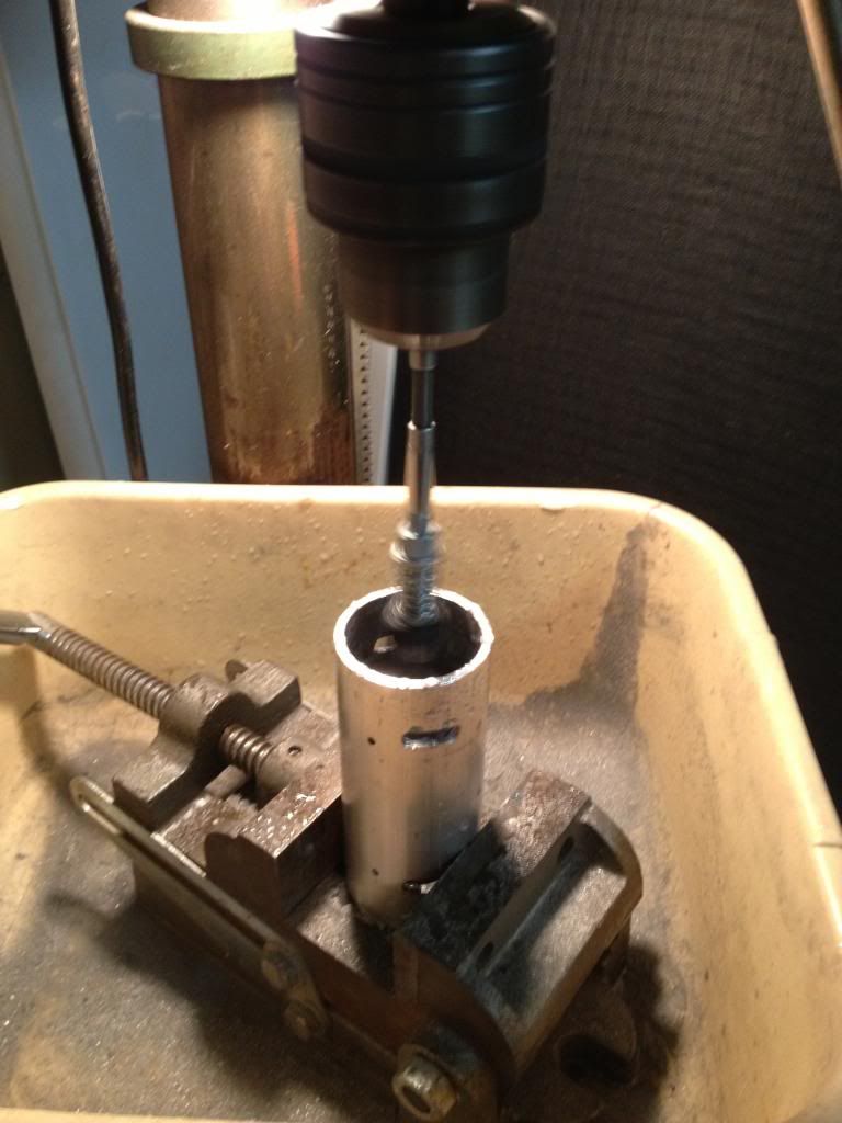
                              Used a brake cylinder hone outfitted with small files, trying to expand the motor cavity a few hundredths of an inch. Close to done, need to do a full install & rotation test.


                              Using spools to wind 4 lower coils and then alternate high half coil and low half coil the rest of the way around.


                              Using Ufo's Quad Pentagon 10-Pole 4-Stator winding design posted HERE.
                              Last edited by sampojo; 06-05-2013, 02:51 AM.
                              Up, Up and Away

                              Comment


                              • @ Richie
                                Machine will get it running great and vary soon. These boards are not forgiving for anything, meaning they work when everything is as JohnStone wrote. There is no allowance for different parts, bad solder joints, smaller than 12 gauge wire from fets to battery cable, not using heat sink when soldering, etc,etc,etc. When he finds the source of that heat, he will be using 15 amps or less. My guess is 11 or less as the higher voltage goes, the lower the amps. That is what I have noted and when one goes from 120v to 240v the amps are cut in half. That is one reason why machines use it. Some machines need more volts to run and ours will probably need 72 at least to get to the top.
                                I have a basic start on an arduino program for the Imperial governor . It is going to be a lot of work in a program called Processing which is the BIGGER BOY of Arduino program. The program must not only do the governing, it must control and read all inputs and outputs as JohnStone has stated, BUT it must monitor all functions as they run and provide a functional fix on the go up to a safe shutdown and this may include a power relay to cut off battery if fets lock on. I do not know if you have had that experience but throwing the arduino across the yard will not stop that motor if fets are locked on. This will be a job of equal time and effort to building the Imperial. I am almost hoping that someone from the Arduino forum would see this as the ultimate challenge and get er done. I do have a copy of a governor program for a saw mill which does all this already but with different sensors and things.
                                Dana
                                Last edited by prochiro; 05-31-2013, 01:24 AM. Reason: spelling
                                "Today's scientist have substituted mathematics for experiments and they wander off through equation after equation and eventually build a structure which has no relation to reality."
                                Nikola Tesla

                                Comment

                                Working...
                                X