Announcement

Collapse
No announcement yet.

My Asymmetric Electrodynamic Machines

Collapse
X
 
  • Filter
  • Time
  • Show
Clear All
new posts

  • Diodes...

    Originally posted by machinealive View Post
    Hey UFO and all

    Well, I've got a panel hooked up just for the setup, a 30 amp input breaker, and 4 @ 15 amp, out. 3 output should be close to 30 amps, then I've got a toaster oven for the final load. The only problem now is I blew up my diodes on the input, after putting them on sinks. Bummer.

    I think I have to try it without the diodes. What do you think?
    Hey Machine!

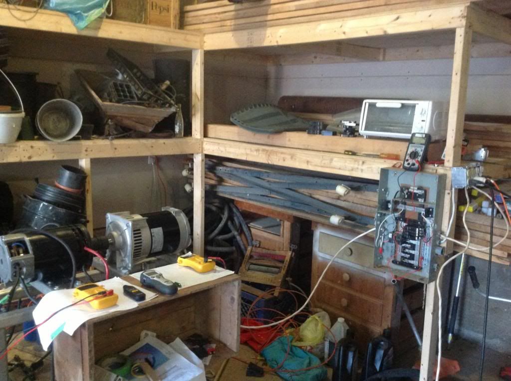
    Nice set up there...now, you are not running Imperial through the Monster Pulsers?...but, through the Liquid Solenoid circuit , right?

    You can run it without diodes, however, commutators will get hot, and amperage will raise...You could use a small but powerful external fan...but amperage will increase when you add loads to Generator Head.

    And the thing is, Imperial will increase its Reversed Generated Energy (Radiant) when it is under a mechanical load, and based on this connection, we are using all gates for Input, so there is no way for Machine to "exhaust" that extra energy, through the Generator Gates, reason why amperage raise.

    You could try using High Wattage CFL's...not incandescent bulbs, as a load to absorb reversed flow, by connecting the CFL's parallel to Diodes, one for each...then diodes may work cooler...try High Wattage CFL's ...not incandescent bulbs.

    However, my Friend...You will need to get Dana's codes...Arduino and Four Monsters...to be fully successful here without "doubts or headaches". Like I wrote in my previews post to you...This is the way to go here, on this Imperial-MeccAlte set up.


    Regards and good testing!


    Ufopolitics
    Last edited by Ufopolitics; 05-06-2013, 06:16 AM.
    Principles for the Development of a Complete Mind: Study the science of art. Study the art of science. Develop your senses- especially learn how to see. Realize that everything connects to everything else.― Leonardo da Vinci

    Comment


    • Uniform Testing on Imperial/Meccalte and Arduino-Monsters Pulsers

      Hello to All,

      This post is mainly directed to Dana (Prochiro), Hitby13kw and if Machine Alive goes this way...or others (not active posting here lately) that are building this set up with Imperial-MeccAlte, Arduino and four Monster Modules.

      This is what I recommend you guys do...in order to make a Uniform Testing with this set up.

      The MAIN Parameters to read at ALL TIMES of Imperial (the basics) are Voltage from batteries or PSU and Amperage draw, as also RPM's at shaft.
      But, on the Electronic Controllers side, we should also measure Frequency, Duty Cycle and the Off Times "gap" between all four channels.
      If You guys could add LED's like you had before, but, at every numbered gate, will be awesome for visual monitoring of the sequence speed...

      1-Once Imperial is mechanically attached to Gen Head, and Electronic Controllers set up ready to go, start dialing potentiometer without adding any loads to Generator untill you reach the 3600 RPM's at shaft-coupler. Then Make a mark on that spot on your Pot Knobs and back plates.

      This way you will know exactly, how far are you turning that knob to satisfy loads to generator, away from that Point, as also every time you restart the system, you will know the point to reach.

      2- Do not add all the loads at once to Generator Head, but ONE BY ONE, knowing the appliance wattage draw or using an Energy Meter. NOW, Very Important here...every time you add a load you will have to dial up that knob again, and depending on Watts consumption you will need to go further and further.

      Here, it is very important to check and write down also, -as you add One by One loads- the required Frequency, Duty Cycle and Off Times parameters difference for every increase of Watts to Generator. This will help Us all to establish the Future Graphics and Data Exchange, between both Machines Future "Communications" .

      So, please, my friends, let's forget about reaching Over Unity...or Perpetual Machines...or Self Runners...and please, let's concentrate in gathering ALL this Data/Information as precisely as you could.

      Your work is VERY, Extremely Important here my Friends, in order to build later on, a smaller, cheaper and much simpler Electronic Controller, that would be a self/automatic unit with direct response to loads as auto/reset when off load...as also all the "Overload" automatic kill switches, etc,etc...to protect machines as to run them without major stresses.

      And...without that Data, you Guys will be collecting out of this testing...it would be Impossible to build such future controllers.

      I really, really appreciate all you guys are doing here, as I am sure off, many others are also thankful of your awesome contribution here ...your building, development and testing of all this Machines, their Controllers...as building from scratch, all other peripheral components... will be the Main Foundation for all others to follow in a near future...and by having clear videos, uniform and scheduled testing, would be much simpler to Replicate your great work .

      On another note, if you guys or anyone else here, would like to add another measurement/data that I may have missed/forgot...please, do so by posting it here to Us all...it will be appreciated.

      Edit1: I forgot to mention measuring temperature as a safety parameter to avoid any accidents, basically at your Inner components like commutators, coils, please!

      Many thanks again, and wishing great and very successful future testings!!


      Warm Regards and Cheers


      Ufopolitics
      Last edited by Ufopolitics; 05-06-2013, 07:39 AM.
      Principles for the Development of a Complete Mind: Study the science of art. Study the art of science. Develop your senses- especially learn how to see. Realize that everything connects to everything else.― Leonardo da Vinci

      Comment


      • Quadra Pulser

        Hello All and UFO

        The Quadra Pulser is functional and I will get it to you by tomorrow if not tonight. The thing that I have been delayed with is testing different ways to control and getting exact accuracy. One thing at a time.
        To use pots as UFO suggested is the only way I can get to work. When using Nico's button with the faster timers produces an exact and fast signal because it uses the built in timers. I can not find a way to get that to work as the signal is totally done within the chip, and can not be manipulated as we need.
        When using the regular timers and "HIGH or LOW" commands we can manipulate the signals as we please. This does have a small drawback because the more code we have in the program and if using a LCD or any other sensor, there is a vary small delay that changes the exact control. This is only One duty cycle or part of a frequency but is still a variable error.
        I will give you the code I have with the idea that someone out there can maybe help with some improvement. IT does work well as coded now but I believe some improvement is possible.
        For those working on the Monster circuit, I do think that only two fets are needed in each of the four drivers when using the Quadra Pulser as the duty cycle is so low per pulse, but four fets for the rest of the Imperial setups are needed for safety.

        Dana
        "Today's scientist have substituted mathematics for experiments and they wander off through equation after equation and eventually build a structure which has no relation to reality."
        Nikola Tesla

        Comment


        • Pot Versus Buttons...

          Originally posted by prochiro View Post
          Hello All and UFO

          The Quadra Pulser is functional and I will get it to you by tomorrow if not tonight. The thing that I have been delayed with is testing different ways to control and getting exact accuracy. One thing at a time.
          To use pots as UFO suggested is the only way I can get to work. When using Nico's button with the faster timers produces an exact and fast signal because it uses the built in timers. I can not find a way to get that to work as the signal is totally done within the chip, and can not be manipulated as we need.
          When using the regular timers and "HIGH or LOW" commands we can manipulate the signals as we please. This does have a small drawback because the more code we have in the program and if using a LCD or any other sensor, there is a vary small delay that changes the exact control. This is only One duty cycle or part of a frequency but is still a variable error.
          I will give you the code I have with the idea that someone out there can maybe help with some improvement. IT does work well as coded now but I believe some improvement is possible.
          For those working on the Monster circuit, I do think that only two fets are needed in each of the four drivers when using the Quadra Pulser as the duty cycle is so low per pulse, but four fets for the rest of the Imperial setups are needed for safety.

          Dana

          Hello Dana!, hello to All,

          I am very glad to "hear" that the Quadra Pulser is functional...(between You and Me...I knew it would be..., but...shhh don't tell anyone else... )
          And...Looking forward to see those videos of the whole thing working together!!...


          Now, related to Pot versus buttons...I like Pot's, mainly because of easier maneuvering and fastest reach to desired spot, like I mentioned in previous post, but, now that you are mentioning the differences between both as buttons using faster -built in microprocessor chip- timers...not working out...I would like to add something here for all to understand one of the possible reasons why...

          Most of the Symmetrical Motors and Generators that we know so far...get their coils to work on a "Full Time Basis", no "brake/idle"...but 24/7 during their operation...so, we are used to winding our Machines the same way that Symmetry has been doing for the last 130 years ..randomly wounds...no winding patterns...just piling wire turns as they "fit" in a narrow "V" Shape Space...and We have been doing it also the same way here...and what happens is...that when a "Too Clean, faster and Sharper" pulsed signal enters a randomly wound coil...it does not creates a solid/strong magnetic field pattern...but also..."a very randomly" displayed/projected, therefore, very weak field...no time to build a solid compact magnetic field strength ...

          Higher Frequency Machines...must be wound in a very uniform, steady and consistent turns order, from start(back) to end(front)...then back to start...then back to repeat same exact winding sequence at every Pair-Coil our armatures require....not randomly wounds...as they will only work with analog or slower electronic timing signals.


          Thanks much for all your work and effort Dana!


          Kind Regards


          Ufopolitics
          Principles for the Development of a Complete Mind: Study the science of art. Study the art of science. Develop your senses- especially learn how to see. Realize that everything connects to everything else.― Leonardo da Vinci

          Comment


          • It get's better and better.

            Great work DANA, can't wait for a vid on pulser, thanks.

            @ UFO, in regards to your post above about winding procedure, for higher frequency pulsed machines, could you please elaborate on the method to use, perhaps with a drawing or something?.

            Much Appreciated,

            Warm Regards Cornboy.

            Comment


            • Quadra Pulser 4

              Hello All
              You may download the code file for the Quadra Pulser here.

              https://www.dropbox.com/s/r0tu175y7j...blink4ver2.ino

              Please note that it should work on any arduino board with 4 or more PWM pins. For testing, (LED and a resistor)X4 should be used.
              Ideas and comments welcome. If you can improve this, do so.
              This is just the beginning of some real life setups. I am milling all four Monsters and there drivers onto one large copper PCB to limit rats nest wire and keep lines short as JohnStone recommended. Also, make sure that when you add the Monsters, that you keep them in the correct firing order (1,2,3,4).
              Enjoy and Improve
              Dana
              Last edited by prochiro; 05-06-2013, 10:54 PM. Reason: Edit
              "Today's scientist have substituted mathematics for experiments and they wander off through equation after equation and eventually build a structure which has no relation to reality."
              Nikola Tesla

              Comment


              • Hi friends,
                chiming in while trying to get track of all posts still missing in my brain. Glad you still proceed
                Nico's setup was invented in order to get the maximum frequency out of Arduino while maintaining precision. Hence a simple pot would not do well because of extremely wide frequncy range Hz ...MHz.
                But very high frequency is not the requirement for current motor setup. Hence a simple pot might do well. I reccomend to add two in series i.e. 10K and 1K in order to have one for coarse (10k) and one for accurate (1K) adjustment.
                You might want to use - alternatively - 10 turn pots


                or gear knobs

                Additionally you could use a set of preadjusted 10 turn trimmer pots


                and switch them to Arduino as requried.
                Keep on good work !

                @DANA: Thanks for your code! I will check it ASAP - for own education first :-(
                @Machine: What type of diodes do you use exactly? Going to check data sheet fo you.
                @ALL:
                - Please try to stay at 2 Infineon FETs per channel. Adding more might slow down the switching time - hence adding heat. Please approach with low duty cycle and variable frequency first and check heat constantly.
                - Test your driver stages with moderate resistive load first!!!!!!
                JS
                Last edited by JohnStone; 05-07-2013, 12:20 PM.
                Experts spend hours a day in order to question their doing while others stopped thinking feeling they were professionals.

                Comment


                • Nice to see you back Sir John Stone!

                  Originally posted by JohnStone View Post
                  Hi friends,
                  chiming in while trying to get track of all posts still missing in my brain. Glad you still proceed
                  Nico's setup was invented in order to get the maximum frequency out of Arduino while maintaining precision. Hence a simple pot would not do well because of extremely wide frequncy range Hz ...MHz.
                  But very high frequency is not the requirement for current motor setup. Hence a simple pot might do well. I reccomend to add two in series i.e. 10K and 1K in order to have one for coarse (10k) and one for accurate (1K) adjustment.
                  You might want to use - alternatively - 10 turn pots


                  or gear knobs

                  Additionally you could use a set of preadjusted 10 turn trimmer pots


                  and switch them to Arduino as requried.
                  Keep on good work !

                  @DANA: Thanks for your code! I will check it ASAP - for own education first :-(
                  @Machine: What type of diodes do you use exactly? Going to check data sheet fo you.
                  @ALL:
                  - Please try to stay at 2 Infineon FETs per channel. Adding more might slow down the switching time - hence adding heat. Please approach with low duty cycle and variable frequency first and check heat constantly.
                  - Test your driver stages with moderate resistive load first!!!!!!
                  JS
                  Hello John,

                  Is good to see you back!, and hoping it means your Family trouble is over, or at least clearing up.

                  That's a great idea to use two Pots in series, using the coarse to get "roughly close" to the required RPM's range, then fine tuning to required draw.

                  I also thought of using a resistor-once the 3600 RPM's spot has been marked and measured its resistance- between Wiper and Higher Resistance side (Opposite side of Gain Speed rotation sense) that could be switch controlled to get a faster reach to that "Idle" point.
                  Would that be something that will also work John?


                  Kind regards


                  Ufopolitics
                  Principles for the Development of a Complete Mind: Study the science of art. Study the art of science. Develop your senses- especially learn how to see. Realize that everything connects to everything else.― Leonardo da Vinci

                  Comment


                  • I love Your "Always Curiosity" Cornboy...

                    Originally posted by Cornboy 555 View Post
                    Great work DANA, can't wait for a vid on pulser, thanks.

                    @ UFO, in regards to your post above about winding procedure, for higher frequency pulsed machines, could you please elaborate on the method to use, perhaps with a drawing or something?.

                    Much Appreciated,

                    Warm Regards Cornboy.
                    Hello Cornboy,

                    They say...that must Scientists and Inventors are very curious people...

                    Ok, you said you like Mechanical Engineering...so I will explain it...in that field of Science.

                    Say we make two compression springs...wound/built with exactly same number of turns, same material spec's...BUT, one of them is wound/formed very precisely ordered, one ring after the other and keeping exactly same distances between them...while the other is NOT done that way...it was formed "randomly"...one turn, then it jumped to form a further ahead turn, to form another ring...then went back and did two more, then all the way to top and turn it three times...so on...in other words...a very lousy build for a spring......but we "managed" to make them both exactly the same length (uncompressed) ...

                    My questions now...

                    If we compress those two springs...with exactly the same pressure force and equally angled vectors (same,exact directions) to both...Do you think they will both project/execute the same reactive force when "decompressing" freely, once suddenly released from that pressure?

                    Now...a "Second Pushing Force" that is applied to both Springs...but this time it is a very High Frequency Pressure/No Pressure Force...

                    Do you think both springs will respond/react identical to that fast actuating force?


                    Now, lets imagine our coils are those two springs...and the Push/Execute Force after released from compression stage... would be their Magnetic Fields ...and...let's figure the "Compressing Force" is the Energizing Power (Pulsed Voltage/Current) we apply "briefly" to our Coils...

                    What do you think?...


                    Warm Regards


                    Ufopolitics
                    Last edited by Ufopolitics; 05-08-2013, 02:43 AM.
                    Principles for the Development of a Complete Mind: Study the science of art. Study the art of science. Develop your senses- especially learn how to see. Realize that everything connects to everything else.― Leonardo da Vinci

                    Comment


                    • Winding.

                      Originally posted by Ufopolitics View Post
                      Hello Cornboy,

                      They say...that must Scientists and Inventors are very curious people...

                      Ok, you said you like Mechanical Engineering...so I will explain it...in that field of Science.

                      Say we make two compression springs...wound/built with exactly same number of turns, same material spec's...BUT, one of them is wound/formed very precisely ordered, one ring after the other and keeping exactly same distances between them...while the other is NOT done that way...it was formed "randomly"...one turn, then it jumped to form a further ahead turn, to form another ring...then went back and did two more, then all the way to top and turn it three times...so on...in other words...a very lousy build for a spring......but we "managed" to make them both exactly the same length (uncompressed) ...

                      My questions now...

                      If we compress those two springs...with exactly the same pressure force and equally angled vectors (same,exact directions) to both...Do you think they will both project/execute the same reactive force when "decompressing" freely, once suddenly released from that pressure?

                      Now...a "Second Pushing Force" that is applied to both Springs...but this time it is a very High Frequency Pressure/No Pressure Force...

                      Do you think both springs will respond/react identical to that fast actuating force?


                      Now, lets imagine our coils are those two springs...and the Push/Execute Force after released from compression stage... would be their Magnetic Fields ...and...let's figure the "Compressing Force" is the Energizing Power (Pulsed Voltage/Current) we apply "briefly" to our Coils...

                      What do you think?...


                      Warm Regards


                      Ufopolitics


                      Hello UFO, and all.

                      @ UFO, so are you saying that when i finally wind the rotor on the MAG3, ( hate labourious work, so am completing the whole motor first, except for winding rotor and stators.), that i should be as precise as possible, and try to make all 36 coil pairs the same and as neat as possible, trying to keep a layered effect, like a standard solonoid winding?

                      If that's not what you mean, please help me to understand correctly UFO, you can never learn too much.

                      Regards Friend, Cornboy.

                      Comment


                      • Originally posted by Cornboy 555 View Post
                        Hello UFO, and all.

                        @ UFO, so are you saying that when i finally wind the rotor on the MAG3, ( hate labourious work, so am completing the whole motor first, except for winding rotor and stators.), that i should be as precise as possible, and try to make all 36 coil pairs the same and as neat as possible, trying to keep a layered effect, like a standard solonoid winding?

                        If that's not what you mean, please help me to understand correctly UFO, you can never learn too much.

                        Regards Friend, Cornboy.
                        Cornboy...

                        Yes, that is exactly what I meant...

                        But, You do not have to do it like that in your machine...unless you are trying to pulse it with High Frequency...something I believe not many have done here...?

                        Besides one main fact Cornboy...no matter how much you try to make one turn after the other...and as precise as you want....wires will always slip and run, or come loose, basically when we pull them with force to make them tight...You may do ok in first pairs...but after a few more pairs wound, and on top of previous coils...it is almost IMPOSSIBLE to do this...simply because the structure We all know so far...is NOT designed to do so.

                        One very simple example...

                        Nikola Tesla designed and Patented a different structured armature cores...

                        Tesla Patent 417,794 - Armature for Electric Machines

                        "...The invention relates to the construction of armatures for electric generators and motors, and the object is to provide an electrically efficient armature, the construction of which is simple and economical, and in which the coils of insulated conducting wire or ribbon may be conveniently wound or formed into bobbins so located with reference to the body of the armature as to afford as good results as possible..."

                        ..."The invention consists, in general terms, in forming an armature-core which is preferably built up of laminae of magnetizable material insulated from each other, with diverging slots or openings for receiving the armature wire or ribbon, which slots are connected with the exterior of the armature by openings through which the wire may be laid in the slots, and in placing the wire in such slots in the proper manner..."

                        And...IF You look closely at Figure 1 at the link above...will notice Tesla creates/designs a "Retaining Bracket/Plate" hold by two screws, RIGHT at CENTER of Coils...(and if you look at FIG 2, will notice this plates are also at bottom of Armature...to keep wires packed in place and evenly positioned, preventing form coming loose at very high speeds.

                        Why do you think Tesla, was so concerned about this detail?...besides the fact of forming the coils as CLOSE as Possible to the OUTER AREA DIAMETER of Armature, making it AS CLOSE AS POSSIBLE to Stators?

                        Symmetry does NOT require that "precision or design" in their windings, since they ALWAYS operate in ONLY ONE huge Coil for two brush two stators Structures...or for the Four Brush Four Stators Systems...NO MATTER how many poles or what size their Motors have/are....So Brushes "Virtually Slice" that MAIN and ONLY COIL in Two or Four Magnetic Poles, respectively, according to brush number.

                        And when you ONLY have ONE MAIN Coil in your whole Machine Armatures....you really do not pay attention/care about this...they will always project strongly because of their big area of Magnetic Interaction and simple configurations....


                        Regards


                        Ufopolitics
                        Last edited by Ufopolitics; 05-08-2013, 04:04 AM.
                        Principles for the Development of a Complete Mind: Study the science of art. Study the art of science. Develop your senses- especially learn how to see. Realize that everything connects to everything else.― Leonardo da Vinci

                        Comment


                        • Hello Joe, (Sampojo)
                          I have used the Leonardo and the Mega 2560 but I think that this program is so generic that it should work on any of them. I use those because they have built in serial support but this really is not needed here. I will soon get the two pulse code out so some one can experiment with the smaller motors using two inputs. Then you can show that you could run the things with less amps than before. Hey, its something to do with your brand new Arduino whatever.
                          Dana
                          "Today's scientist have substituted mathematics for experiments and they wander off through equation after equation and eventually build a structure which has no relation to reality."
                          Nikola Tesla

                          Comment


                          • Awesome Dana!!

                            Originally posted by prochiro View Post
                            Hello Joe, (Sampojo)

                            I will soon get the two pulse code out so some one can experiment with the smaller motors using two inputs. Then you can show that you could run the things with less amps than before. Hey, its something to do with your brand new Arduino whatever.
                            Dana
                            Hey Dana,


                            Now, that IS AWESOME!...As it will demonstrate at lower scale...for those that are not working with Imperial!!

                            YES, It will demonstrate the Amperage reduces even with two pole machines...when comparing it to "Normal-Even" Pulses to both Gates.
                            As to also say...that Speed and Torque Increases instead of coming down...

                            Love it!!...can't say it is a F******G awesome idea...but we can not write bad words here...

                            Awesome work you are doing!!...please take goood care of yourself...We need you here!


                            Warm Regards My Friend!


                            Ufopolitics
                            Last edited by Ufopolitics; 05-08-2013, 04:14 AM.
                            Principles for the Development of a Complete Mind: Study the science of art. Study the art of science. Develop your senses- especially learn how to see. Realize that everything connects to everything else.― Leonardo da Vinci

                            Comment


                            • Hmmm

                              Hey UFO, that patent extract is fantabulous, i am struggling to track where exactly the wires run in the rotor. Am really busy now, will study further and get back to you, Thanks.

                              Warm Regards Cornboy.

                              Comment


                              • Fantabulous?!

                                Originally posted by Cornboy 555 View Post
                                Hey UFO, that patent extract is fantabulous, i am struggling to track where exactly the wires run in the rotor. Am really busy now, will study further and get back to you, Thanks.

                                Warm Regards Cornboy.
                                Fantabulous?!...
                                Principles for the Development of a Complete Mind: Study the science of art. Study the art of science. Develop your senses- especially learn how to see. Realize that everything connects to everything else.― Leonardo da Vinci

                                Comment

                                Working...
                                X