Announcement

Collapse
No announcement yet.

My Asymmetric Electrodynamic Machines

Collapse
X
 
  • Filter
  • Time
  • Show
Clear All
new posts

  • Nice Videos!

    Originally posted by machinealive View Post
    Hi everyone'

    Here are some vids of the mecc alte setup. not much but i'm going to start loading more, and put a 40 amp breaker across gen.

    Mecca alte setup #1 - YouTube

    mecc alte running
    Mecc alte with small load - YouTube

    at night to see lighting
    Mecc alte - YouTube

    peace


    Hey Machine!!


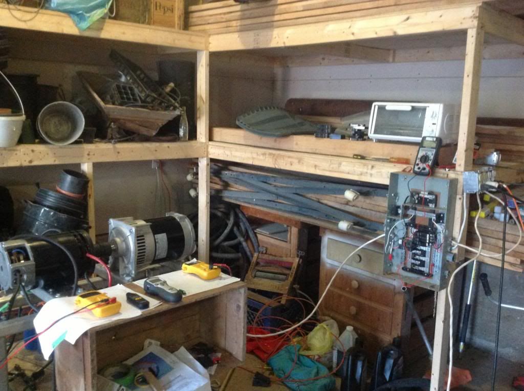
    Yes, your measurements are all correct...you have RPM's on the right spot, meaning your Imperial is very fine tuned.

    A couple of things here...

    1- The measurement of the MeccAlte Cap...is not its Output, it is the exciting fields voltage. So try to get a reading off the Total of both Generating coils lives (blacks and/or red) and the neutral (whites) as common, like reading 240 Volts.
    Then read Amperage between the loads and live wires (remember to switch your clamp meter, back to AC Amps)

    Your Machine sounds awesome!


    Warm Regards my friend, and again, great to see you back...NOW, between Hitby13kw, Dana (Prochiro) and You...the Imperial-MeccAlte deal will make lots of progress....am sure off!


    Ufopolitics
    Principles for the Development of a Complete Mind: Study the science of art. Study the art of science. Develop your senses- especially learn how to see. Realize that everything connects to everything else.― Leonardo da Vinci

    Comment


    • Great Approach.

      Originally posted by Hitby13kw View Post
      Hello all,

      Finally got my motor on a stand with the Genhead, took a quick vid of it running ( just to show that it does) will start doing more testing to take a hard look at power in/out - For this run we did not pulse the gates, they were tied directly to a DC supply putting in 44V @ 23.7 A that’s 1042.8 W the motor was spinning at 2800 RPM with no load on the genhead

      Could be better, but it's spinning and relatively balanced. https://www.dropbox.com/s/arhva7hvvm5eg56/SAM_0139.AVI

      any and all comments about the UFO motor welcome and wanted,
      for the single to 3 phase converter lookup rotoverter / Hector Torres (this is not the time or place)

      Hitby13kw
      Hello Hitby13kw,

      Great work!

      The incorporation of a PSU to run Imperial is the PERFECT way to do it for this testing stages...it is just a possibility we all do not have...but is great you do have it and using it!

      Now, you still need to make some more tuning to Imperial Timing (I know you know that, just posting here for others to read)...at 44V and 23 Amps it should have gone much higher than that with no load at Genhead.

      You could also test RPM's at same set up but, with batteries...making sure the PSU is outputting whatever is showing on its screen.

      On the "General View", you are on the right/perfect tracks here, related to other posts you have written about using "Transformerless" Converters...as also Transformer-less PSU's...A Transformer-less Unit...is nothing more than a "Switching Through FET's/Inductors/Diodes Technology"...very efficient units...no heat/magnetic fields/flux loss from huge dinosaurs Transformers...

      The goal here would be a very low wattage consuming Switching PSU, that outputs Imperial Wattage draw...in order that batteries could be used as a starter source only...then recharged and maintained for the minimal loss of the initial starting period through another "switching tech" BMS (Batt Management System).

      Fusing Solar as an assisting source (as it could also be wind or water falls) will provide the robustness we need.


      Looking forward to see your set up being pulsed/ran through Arduino-Monster Pulsers with Dana's Program...


      Warm Regards


      Ufopolitics
      Principles for the Development of a Complete Mind: Study the science of art. Study the art of science. Develop your senses- especially learn how to see. Realize that everything connects to everything else.― Leonardo da Vinci

      Comment


      • Symmetric Brushless Generator Main Concept(s)

        Hello to All,

        It is good to know how our Generator Heads work, basically the Brushless technology ones like Mecc Alte...

        The Patent shown below reflects the Basic Principle behind all Brushless Alternators/Generators based on Capacitor Excited Fields.

        [IMG][/IMG]

        Complete Patent could be found below:

        https://docs.google.com/viewer?url=w.../US4786853.pdf

        I have added the text pointing AT main components.

        The only differences that we could find related to Mecc Alte are:

        [IMG][/IMG]

        1- Mecc Alte have Two separate Looped Coils through Diodes, per Pole at Rotor and a Varistor or Movistor in parallel to keep voltage/currents/magnetic field constant....that will render a constant N-S per pole.
        -On this Patent, there is only One Diode looping two coils N-S-.

        2-The exciter field is just one in Mecc Alte, not different ones like shown here on this patent.

        3-The Generating Fields are not Internally joint by a common/split side, but instead, two separate Coils that we join externally. (Four Wires Out)

        Despite of all this differences...the main "essence" of this Patent is exactly the same thing as all Capacitor Excited Brushless Alternator/Generators.

        So, basically, and resuming we have...

        A-The Stator-Rotor consists of a Looped/Closed Coil through a Diode, where diode guarantees "one flow", therefore, A steady magnetic polarity projected at poles.
        B-The Exciter Fields are also based on Looped Coil(s), except that instead of a Diode...a Capacitor keeps feeding them constantly as exciter coils magnetic fields keep Inducing a Current at spinning Stator(s)
        C-And, like any other Generator out there...Spinning Stator Induces a Current/Voltage at Output/Generating Fields...

        And so on and on...the process repeats over every cycle...

        This Patent is now (since 2008) Public Domain, because it expired its 20 years protection...


        Regards to All


        Ufopolitics
        Last edited by Ufopolitics; 04-30-2013, 09:28 PM.
        Principles for the Development of a Complete Mind: Study the science of art. Study the art of science. Develop your senses- especially learn how to see. Realize that everything connects to everything else.― Leonardo da Vinci

        Comment


        • mecc alte runs - Nice

          Originally posted by machinealive View Post
          Hi everyone'
          Here are some vids of the mecc alte setup. not much but i'm going to start loading more, and put a 40 amp breaker across gen.
          Mecca alte setup #1 - YouTube
          mecc alte running
          Mecc alte with small load - YouTube
          at night to see lighting
          Mecc alte - YouTube

          peace

          machinealive1 nice to see on the list again, watched your newest runs – just love the mercury emergency cutoff (may have to incorporate something like that into my setup) can’t be to safe.
          As to your diodes that are getting hot, don’t get rid of them, put them on a heat sink (I know that you know that)
          Very nice work !!! Thanks for sharing
          Hitby13kw

          Comment


          • RPM's nailed.

            Welcome back Machine, and thanks for the vid's, well done.
            Looks a bit warmer there now. It will be interesting to see amps when you pulse that sparking Beast, especially if it's with Monsters.

            I'm glad you found some time to get back on to it, i'm struggling at the moment, extremely busy times.

            Warm Regards Cornboy.

            Comment


            • Hello UFO, everyone

              Didn't have much time previously, just enough time to post videos.
              Thanks for the schematics UFO, I kept meaning to look that up. I'll put the meter across output at switch, not cap.
              Hitby13kw, it was good to see your gen spinning. You inspired me to finish hooking up the alte.
              Hey cornboy, yes it's nice now, my plum and cherry trees are just getting ready to pop, the chickens love the new green grass, yolks are dark orange again, I'm lovin' it.

              I want to see how much I can load up at 72v 50-55amps, try to blow a 30amp breaker at 120v. That would be a good start. The bandsaw and lights hopefully drew around 11 amps, and it dropped the rpm from 4100 to about 3600 rpm. 72v will spin it 5000 rpm, unloaded. I hope I can draw over 30 amps, and only drop from 5000 to 3600 rpm. That's my little plan right now, it will be nice to know, then go back to driving.
              Thanks Dana, your codes will save a lot of time.

              Cheers

              Comment


              • Hey Machine...

                Originally posted by machinealive View Post
                Hello UFO, everyone

                Didn't have much time previously, just enough time to post videos.
                Thanks for the schematics UFO, I kept meaning to look that up. I'll put the meter across output at switch, not cap.
                Hitby13kw, it was good to see your gen spinning. You inspired me to finish hooking up the alte.
                Hey cornboy, yes it's nice now, my plum and cherry trees are just getting ready to pop, the chickens love the new green grass, yolks are dark orange again, I'm lovin' it.

                I want to see how much I can load up at 72v 50-55amps, try to blow a 30amp breaker at 120v. That would be a good start. The bandsaw and lights hopefully drew around 11 amps, and it dropped the rpm from 4100 to about 3600 rpm. 72v will spin it 5000 rpm, unloaded. I hope I can draw over 30 amps, and only drop from 5000 to 3600 rpm. That's my little plan right now, it will be nice to know, then go back to driving.
                Thanks Dana, your codes will save a lot of time.

                Cheers

                Hey there Machine,

                Yeah, the voltage at Cap ranges from 300 to 500V, depending on load demand at output coils.

                But talking about Imperial...Your Machine seems to be in optimal tuning spec's...and when you drive it with the four monster modules...based on Dana's Codes...and Arduino's Microprocessor...that would be an awesome run!

                Your Amperage would reduce to 1/4 of whatever it is now...or what is equivalent to run your Imperial based on just ONE Gate feed. (try feeding your motor by just, say P1, then measure amps...

                The Main idea of the dead/off times (don't know if you had time to read my previous posts) is to achieve One Pulse at a time/One Gate at a time, that fires in a Sequence every 90º of the 360º(say P1=0º,then P8=90º, then P15=180º and P22=270º, then back to 360º=0º or P1[start new cycle])...and by increasing firing frequency (getting On Times closer) it will accelerate machine beyond expectations...and with very low amp draw...

                This is the way to go here...my friend.


                Warms regards


                Ufopolitics
                Last edited by Ufopolitics; 05-01-2013, 05:17 PM.
                Principles for the Development of a Complete Mind: Study the science of art. Study the art of science. Develop your senses- especially learn how to see. Realize that everything connects to everything else.― Leonardo da Vinci

                Comment


                • Vortex Rotor Core...

                  Hello to All,

                  VORTEX ROTOR CORE - YouTube

                  Enjoy and Regards


                  Ufopolitics
                  Principles for the Development of a Complete Mind: Study the science of art. Study the art of science. Develop your senses- especially learn how to see. Realize that everything connects to everything else.― Leonardo da Vinci

                  Comment


                  • Excellent.

                    Originally posted by Ufopolitics View Post
                    Hello to All,

                    VORTEX ROTOR CORE - YouTube

                    Enjoy and Regards


                    Ufopolitics


                    Beautiful UFO, that's my next job, it will be a little while though.
                    Looks like a very different winding pattern of the coil pairs, and a definite one direction of rotation.

                    Video is great, my friend, thanks.

                    Warmest Regards Cornboy.

                    Comment


                    • Originally posted by Ufopolitics View Post
                      Hello to All,

                      VORTEX ROTOR CORE - YouTube

                      Enjoy and Regards


                      Ufopolitics
                      Ufopolitics,

                      You keep raising the bar in a good way!

                      Greatly applying your skills in all areas for the benefit of all.

                      Much appreciated,

                      IndianaBoys

                      Comment


                      • What's up, Doc Ufo

                        So Ufo, I was checking N. Tesla Patent 390414, and I couldn't find the dwg of the motor with the double commutators on patent copies available online.


                        Is there another source for this dwg?

                        Making headway on by 4-stator machine. Did the ceramic magnet cuts on my Home Depot diamond blade water cooled ceramic saw that you reminded me that I even owned one. End result not another nickel spent. I like that. So here it is with the magnets on the rotor.


                        Notice how I have no space between the magnets. I notice how the imperial has spacing and all your stators in your drawings have spacing between the magnets. I plan to anchor the magnets with clamps on slots I have made at the end of each magnet, so I don't need spacing to hold them in place


                        I thought that I would have more magnet this way, and the more magnet the better. Ufo, is this a good idea for a motor design?

                        Just wanted to share a good book I thought all readers of this forum would enjoy, as I know it impossible to build assymetric motors every waking minute of the day

                        The Hunt for Zero Point Energy by Nick Cook, published 2000. I bought it used from an Amazon partner hard back for $7! This guy is an editor at Jane's Defense Weekly, one of worlds best aviation, space and military technology magazines. The book reads like one of the most intriguing sci-fi whodunnit villain thillers novels, but as usual truth is stranger than fiction. And we all kinda know story line here on this forum, and its all sad but true, and still rates way up there on the eye-opener rating even for us bleery-eyed web-thread-heads. But of course as a published footnoted documented non-fiction book by a prominent technical journalist of outstanding reputation in the real world, way easier to verify what is true...
                        Last edited by sampojo; 05-05-2013, 03:36 PM.
                        Up, Up and Away

                        Comment


                        • Hello there

                          Originally posted by sampojo View Post
                          So Ufo, I was checking N. Tesla Patent 390414, and I couldn't find the dwg of the motor with the double commutators on patent copies available online.


                          Is there another source for this dwg?
                          Hello Sampojo,

                          Patents do not disclose spec's of any type...that is a General Legal Rule in order to guarantee protection against infringement.
                          The more "general" a patent is...the stronger/larger it makes it scope against someone just changing any given parameter...and it would be a different patent....it may face some "conflicts"...but if motioned it could get granted...stupid, I know...but that's the way legal PTO works.

                          Making headway on by 4-stator machine. Did the ceramic magnet cuts on my Home Depot diamond blade water cooled ceramic saw that you reminded me that I even owned one. End result not another nickel spent. I like that. So here it is with the magnets on the rotor.


                          I am very glad my advice worked out and saved you time and money...

                          Notice how I have no space between the magnets. I notice how the imperial has spacing and all your stators in your drawings have spacing between the magnets. I plan to anchor the magnets with clamps on slots I have made at the end of each magnet, so I don't need spacing to hold them in place


                          I thought that I would have more magnet this way, and the more magnet the better. I this somehow wrong in motor design?
                          In the Designs I have presented here, most of them are based on already existing Symmetrical structured motors...so, I am just reproducing the way Stators are ...

                          It is just fine/perfect and it makes Interactions MUCH Stronger to build Stators without ANY Gap.

                          Symmetry can not afford to do that...because of the "Virtual Steady Symmetrical Rotor Fields"...so they need a separation between Stators, as there is another "virtual separation" between rotor fields, right at the 180ª-90º apart brushes, depending on two or four...forming a "Symmetric Cross" (+) with stators. In Symmetry the brushes establish the Symmetrical Plane or Division line between magnetic poles at the Armature Field.

                          On Asymmetry...occurs a different approach, so the closer stators are, the stronger that asymmetrical interactions will take place...from a repulsion to attraction or viceversa...

                          Now, on other note...and I really hate to say this...but I do not like your "groove" at a ceramic magnet to hold it through a bracket...with vibration...your very brittle ceramic magnets will eventually crack loose...So your best option here would be to glue them together.

                          FASTENAL sells a LOCTITE Glue, specifically designed for Motors ceramic magnets...it is a two part (not epoxy resin)...where one is the activator or adhesion promoter (loctite product#7380) and the actual glue (Loctite part#392)

                          Fastenal part#'s:

                          1-Adhesive 01506462
                          2-Activator 0150254

                          Not cheap at all...but one will make a few hundred motors, since all you do is "brush and spread" a thin coat of both compounds. activator first...then glue......I have used it many times...and tell you it is the best one you could buy...

                          Just wanted to share a good book I thought all readers of this forum would enjoy, as I know it impossible to build asymmetric motors every waking minute of the day

                          The Hunt for Zero Point Energy by Nick Cook, published 2000. I bought it used from an Amazon partner hard back for $7! This guy is an editor at Jane's Defense Weekly, one of worlds best aviation, space and military technology magazines. The book reads like one of the most intriguing sci-fi whodunnit villain thillers novels, but as usual truth is stranger than fiction. And we all kinda know story line here on this forum, and its all sad but true, and still rates way up there on the eye-opener rating even for us bleery-eyed web-thread-heads. But of course as a published footnoted documented non-fiction book, way easier to verify what is true...
                          Sounds like a very exciting book!!, thanks for sharing it here!...


                          Regards and


                          Ufopolitics
                          Last edited by Ufopolitics; 05-05-2013, 10:52 AM.
                          Principles for the Development of a Complete Mind: Study the science of art. Study the art of science. Develop your senses- especially learn how to see. Realize that everything connects to everything else.― Leonardo da Vinci

                          Comment


                          • Hey UFO and all

                            Well, I've got a panel hooked up just for the setup, a 30 amp input breaker, and 4 @ 15 amp, out. 3 output should be close to 30 amps, then I've got a toaster oven for the final load. The only problem now is I blew up my diodes on the input, after putting them on sinks. Bummer.

                            I think I have to try it without the diodes. What do you think?

                            Comment


                            • UFO, Thanks for the tips!

                              Originally posted by Ufopolitics View Post

                              It is just fine/perfect and it makes Interactions MUCH Stronger to build Stators without ANY Gap.
                              thanks, looking for every advantage!

                              Originally posted by Ufopolitics View Post
                              Now, on other note...and I really hate to say this...but I do not like your "groove" at a ceramic magnet to hold it through a bracket...with vibration...your very brittle ceramic magnets will eventually crack loose...So your best option here would be to glue them together.
                              As I tell my co-workers NP! Lay it on me.

                              Originally posted by Ufopolitics View Post
                              FASTENAL sells a LOCTITE Glue, specifically designed for Motors ceramic magnets...it is a two part (not epoxy resin)...where one is the activator or adhesion promoter (loctite product#7380) and the actual glue (Loctite part#392)

                              Not cheap at all...but one will make a few hundred motors, since all you do is "brush and spread" a thin coat of both compounds. activator first...then glue......I have used it many times...and tell you it is the best one you could buy...
                              Might go for it. I was thinking about using this E6000 glue you can get at AC Moore. Not quite as tough as the magnet stuff which I have a lot of respect for after removing these The mechanical fasteners were because I just didn't trust just glue, at least the E6000.

                              I am compiling a reference document for the thread and just wanted to know where the double commutator dwg came from if not patent 390414.

                              No sweat about it though!

                              looking forward to hearing from the big three this week Dana, machine and Hitby!! Good Luck guys!
                              Up, Up and Away

                              Comment


                              • Tesla Patent

                                Originally posted by sampojo View Post
                                I am compiling a reference document for the thread and just wanted to know where the double commutator dwg came from if not patent 390414.

                                No sweat about it though!

                                looking forward to hearing from the big three this week Dana, machine and Hitby!! Good Luck guys!
                                Hey Sampojo,

                                I misunderstood the term dwg by awg...thought you misspell it.
                                So you mean Drawing.

                                Ok the Tesla Patent where I got that "dwg" is 390721

                                Can see it complete here:

                                Tesla Patent 390,721 - Dynamo-Electric Machine

                                Thanks, and yes, am also waiting on this Great Guys to run Imperial with the John Stone Monsters...

                                Cheers

                                Ufopolitics
                                Principles for the Development of a Complete Mind: Study the science of art. Study the art of science. Develop your senses- especially learn how to see. Realize that everything connects to everything else.― Leonardo da Vinci

                                Comment

                                Working...
                                X