-
-
Hi Guys,
3-pole motor with 0.21mm wire 50 turns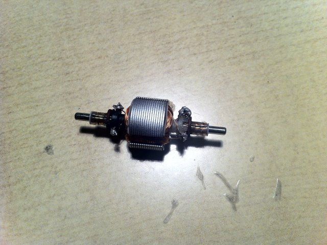
Regards
AceComment
-
Resistance...
Originally posted by Ace_Propulsion View Post
Hello Ace, Cornboy, Kogs...and all,
Ok...the Resistance...and how to...
First, let me tell you...the resistance in that 5 poles Dual Penta in video, have 3.2 to 3.4 ohms per Pair. It was wound with 30 awg (red wire from Radio Shack...)
Now...when it comes to small number of poles...like 3, 5...and so, I recommend to go higher than 1.0.
And when your Motor have 28 poles...36...or even 20..THEN you can "afford" to go at values below 1.0 and even below 0.5
Please, I want to make sure you understand there is a very strict ratio to "obey" here. I use 1.0 Ohm as a Guide...a Borderline to maintain in consideration.
As it also depends upon the power source your motor will be working at. So, if it will work on 3.0 Volts...and mA...then you should try to keep it LOW...otherwise it would be very slow and weak.
Remember that Resistance is in constant "play" with Voltage and Amperage...remember Ohm's Laws...remember Kirchhoff Laws, when our coils in the Machine are "momentarily" closed during rotation intervals.
So, please, don't...establish "Rigid" Parameters for resistance here...they are Dynamic and very "Flexible"...
Resistance is like a "Balance" that you should try...and try different options then test to your application...till you find the suitable performance and behavior of your Motor.
Hope you guys understand me well.
Kind Regards
UfopoliticsPrinciples for the Development of a Complete Mind: Study the science of art. Study the art of science. Develop your senses- especially learn how to see. Realize that everything connects to everything else.― Leonardo da VinciComment
-
Ok Ace,Originally posted by Ace_Propulsion View Post
Here you made it on 0.7ohms...on just three poles motor.
If you plan to run this motor on low voltage...3V,6V...and even 12V...it will be fine...But, if the 12V Battery is too high on Amps discharge(like a Car Battery)...it will fry it.
And understand if you go 24...it would be toasted well done...
If You want your motor to run on different voltage levels...and be safe...then go above 1.0 Ohms per coil...if you have to use a finer wire...do it...
And IF You want to make it really "safe"...I would go up to 1.5 to 2.5 ohms
Hope you guys understand this.
UfopoliticsPrinciples for the Development of a Complete Mind: Study the science of art. Study the art of science. Develop your senses- especially learn how to see. Realize that everything connects to everything else.― Leonardo da VinciComment
-
Excellent Dana!
Originally posted by prochiro View Post
Great Dana!
Nice...She is running like a charm now.You should try to add a mechanical load and observe behavior on amps.
Give it a try with P1-P15 in Parallel...with 36 Volts and the pulser to accelerate the two chanels, then add a mechanical load.
Observe Amps and RPM's
See, we need to keep a compensation value here, when applying a load (mechanical)...remember that Meccalte is gonna add it anyways.
So in this video you started pulsing up to max...right?...then turn switch on-off from pulser that was at high duty cycle?...Am I right?
If so...it should NOT be done like that...You should use the pulser to gain or lower RPM's...without "abruptly" cutting off power from pulser through switch (you could also damage FET's or else, when turning on switch...Spikes would be storing within coils and ready to burst out)
Regards friend
UfopoliticsPrinciples for the Development of a Complete Mind: Study the science of art. Study the art of science. Develop your senses- especially learn how to see. Realize that everything connects to everything else.― Leonardo da VinciComment
-
Hi friends!
I am not lost but lost in my daily tasks but still watching our thread on a regular basis. Dana, congratulation fo your success!
I still ponder on quadradelay and hexadelay (hi Cornboy) pulser if I have some spare time.
I imagine to derive those 4 or 6 signals from the main signal.
The maximum frequency of quadra- and hexa-signal will be less than Nico's pulser but still far more than needed for our motors.
Their maximum pulse width will be restricted to obviously 25% duty (16,6% for MAG3) and additionally by the adjustable delay.
Still pondering on how to deal with pulse width particularly.
A)
Duty cycle will be held constant as adjusted but adjustement will be restricted to 25% minus contribution of delay. There are two drawbacks:
Adjustment for low rpm (restriction from excessive current) will not give enough power at high speed. Conversely adjustement for high speed will cause excesssive current at low speed.
B)
We do not deal with duty cycle but with constant pulse width. Once adjusted for low rpm preventing excessive current it will stay constant in time at increasing frequency thus increasing duty cycle automatically. At a certain frequency the preadjusted delay time will be violated. Then the pulse time will be cut away in order to obey delay time.
The advantage is that the motor can start smooth while getting throttle at higher rpm automatically.
It is essential to get it right from the very start. What is the way to go?
BTW: I am a very poor red necked programmer and it will ease programming considerably if we have clear requirements before starting.
JSLast edited by JohnStone; 04-12-2013, 08:09 PM.Experts spend hours a day in order to question their doing while others stopped thinking feeling they were professionals.Comment
-
Ooopps.
Originally posted by Ufopolitics View Post
Sorry Ace, looks like i gave you a bum steer, on the resistance.
Just my lack of electrical knowledge showing through.
@ UFO, begining to understand, as you know mechanical things are my strong points.
Regards Everybody, Cornboy.
PS. hello John Stone, glad to hear from you, was getting worried when you weren't posting.Comment
-
Kog's Happy UFO Motor
Hello UFO
Over the last year, since Kogs Happy UFO Motor diagram was presented, a lot of changes have been presented. In my memory, that coil caused a lot of heartache and a lot of additional power. My question is could we still take advantage of producing a matched coil set now and if so would that interfere with where we are going or not. If you felt it would be good then I would restudy dynamics of the coil and test that. If not, then I will put it out of my head and continue with putting a load on the Imperial of a small generator head, maybe of 2400 or 3200 watts.????????? Would not a smaller head require less drive?
Dana"Today's scientist have substituted mathematics for experiments and they wander off through equation after equation and eventually build a structure which has no relation to reality."Nikola TeslaComment
-
Good to see You back, John.
Originally posted by JohnStone View Post
Hello John, is good to see You back!
Ok, it seems you are still (pondering now) on this signals...and the delay time.
The FIRST thing here, that I would love you could understand is:
1- FIRST MAIN PART to understand here...IS that the Dead/Delay/Off-set Time...is COMPLETELY an "Issue" between signals...NOT "WITHIN" Signals.
Therefore it should NOT affect at all, the independent parameters of each signal, like Duty Cycle and Frequency.
IF You keep "mixing" Delay Time within the signal parameters (Meaning, Freq & Duty Cycle)...you will keep being confused here.
2- The Delay Time is a Completely Dedicated Parameter, that only exists between Channels.
Say we regulate all Four or Six Channels at EXACTLY SAME Frequency and Duty Cycle...say 50% and 1 Khz...great, so here we adjust our Motor speed...and so...BUT:
Each Signal outputs the same pulsing BUT at separated times between them all....I am talking the time when they start that "Race" to Pulse the FET's Gate Signals...1 starts(delay),2 starts(delay),3 starts (delay), 4 starts (no delay needed here)...Actually, between Four Channels there are only Three delay times required....as for Six there would be only Five required.
Let's Imagine a Race...where there is NOT one Gun Shot for all racing cars to GO at the same time...BUT instead there is a Gun Shot for each Team/Car...(let's paint it here...say each car have a color...and each Gun Shutter Guy is dressed with the respective Car color)...so the First Gun Shot will order Car#1 to leave...then Second shot...second car...and so on...with a delay time between shots...Now, each car will accelerate and maintain a speed which would be exactly the same through the whole race...so...what keep them apart?...the delay time at the starting point. (I know it is a "retarded/stupid" race...nobody wins... )Now, here...IF We accelerate same way, all four cars (say they are remote controlled...and speed regulated by ONLY one throttle Knob...no matter how we try...they will always keep A distance between them. That is what I want here as a delay time.
Resuming here...the Motor Speed that is regulated by Duty Cycle plus Frequency, could be, (and I believe MUST BE) exactly same for all channels, and the reason why I mentioned Four Pulsers...is because they need to turn On-Off those switches at different timing...just one Monster Module could not do this. So the signal...The low voltage signal sent to their Gates Circuit...is the one that must maintain a Delay from the starting point ONLY between each Module...And as I understand here...that is an "Issue" of the Arduino Program to run Microprocessor...and it has absolutely "nada/nothing" to do with each Monster Pulser Module..they are only the "Actuators" to execute the signals... WHENEVER sent.
Hope you see it better now my friend.
Regards
UfopoliticsPrinciples for the Development of a Complete Mind: Study the science of art. Study the art of science. Develop your senses- especially learn how to see. Realize that everything connects to everything else.― Leonardo da VinciComment
-
Happy Motor...
Originally posted by prochiro View Post
Hello Dana,
The Happy Motor Coil-Circuit works fine...I have only test it at a small scale though...and like I wrote back then....There is a DELAY...when we accelerate our pulses on Primary...to where Motor is attached at the other end. This fact creates very slow responses when we are talking about the network/language required between Prime Mover and Generator.
I mean, you could give it try working with this method...and see if a betterment could be done...
But, so far I see you are driving on the right track ...and like you wrote above...trying a lower KW Generator Head is a VERY Smart way to Test here...then see what happens...
We are trying to "Match" Two Machines that were NEVER Matched before, as far as demand from one and response from the other one...and, IF we are below or over spec's ...they will not perform as expected. Remember Generator Heads demand/requires up to certain HP MIN. to run them properly.
Regards
UfopoliticsPrinciples for the Development of a Complete Mind: Study the science of art. Study the art of science. Develop your senses- especially learn how to see. Realize that everything connects to everything else.― Leonardo da VinciComment
-
Hello UFO
That's it, I am mounting the small head tonight and will try it in the morning without cap charged. Could you briefly tell me how to start the cap, if not I will Google something.
Dana"Today's scientist have substituted mathematics for experiments and they wander off through equation after equation and eventually build a structure which has no relation to reality."Nikola TeslaComment
-
Jump starting cap
Hello Dana,Originally posted by prochiro View Post
It depends...is the Generator Brushless?
If the Cap is Polarized, (Electrolytic) showing positive-negative and it has diodes...then, there is NO charging/jumping on this type. They excite by magnetic residue on its rotor/stator core.
If it is an AC Cap...non polarized, just like the Meccalte...then you just connect it for a second to a 120V AC outlet with a couple of connectors and already hooked to exciting fields. Rotor will "jump" first when connected...that is it.
Regards
UfopoliticsPrinciples for the Development of a Complete Mind: Study the science of art. Study the art of science. Develop your senses- especially learn how to see. Realize that everything connects to everything else.― Leonardo da VinciComment
-
Generator Head Powered UP
Hello UFO
After dry walling all day I had a few minutes to power up the Imperial to the generator.
The generator is a 2500 watt 3600 recommended RPM and is single phase. I was using the same wiring setup we did last with the switch on P15. I got it up to about 3300 RPM and the light that was pluged into the generator went on. At 3490 RPM, which was tops with this setup, I measured 70 volts on the gen and was using 15 Amps at the Imperial. Tomorrow will try some other things but she does not seem to be using any more amps with or without the gen using this low load. She does seem happy now that she can carry a load with no stress. Once I get wires cleaned up and maybe higher RPM, I thing 3600 will do it, I will video the run with load attached. Everything is running cool, even the diodes. As you say, WE ARE VARY NEAR OUR BASIC GOAL.
Dana "Today's scientist have substituted mathematics for experiments and they wander off through equation after equation and eventually build a structure which has no relation to reality."Nikola Tesla
Comment
-
Hello Dana
Originally posted by prochiro View Post
Hello Dana,
Hey that's great!
Now, may I suggest you do the following testing:
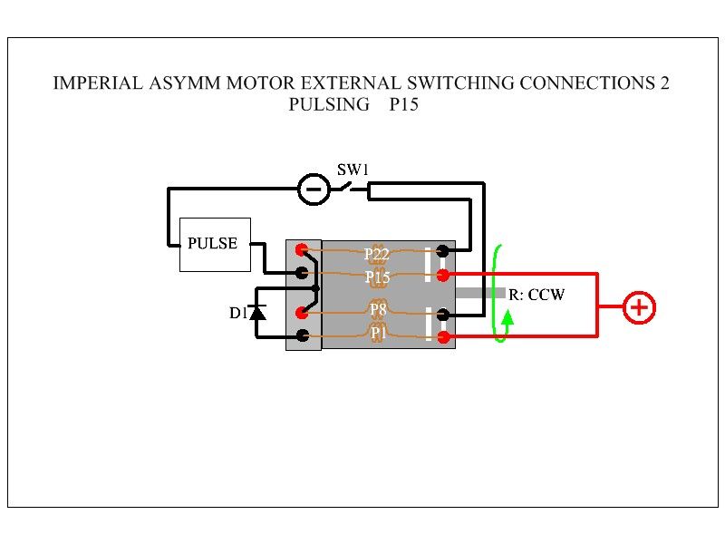
Disconnect Pulser from P15 and Negative...then add a switch there to feed P15 Straight, and after you've got the motor running with P1...Turn on that switch.
If You get over the 3490 RPM's that she did with pulser...say 3600 to 4100, then you have either an adjustment issue on Times On/Duty Cycle...or something else at pulser is not delivering a full and steep constant On Time.
On the other hand...with Generator Head:
It should deliver more than just 70V at 3490 RPM's (You should either add an Energy Meter...or measure amps also)...see, Gen Heads have a RANGE...not an specific and firm RPM of 3600...but a range that goes from 3200up to 3800 RPM's it will still do ok...so check that Gen is working fine also.
Looking forward to watch video!
And yes...we are very close!

UfopoliticsPrinciples for the Development of a Complete Mind: Study the science of art. Study the art of science. Develop your senses- especially learn how to see. Realize that everything connects to everything else.― Leonardo da VinciComment
-
Hello UFO
On that gen head, the voltage was going up fast while I went from 3000 to 3490 RPM. In that the setup was set as it was, I just ran out of ability to raise RPM just 100 more. From what I was seeing, that little extra RPM will shoot voltage to max.
If I understand you correctly, direct feed P1 and P15 but with switch on P15. I will set it up with switches on all P's and record data.
Dana"Today's scientist have substituted mathematics for experiments and they wander off through equation after equation and eventually build a structure which has no relation to reality."Nikola TeslaComment
 Tweet
Tweet
Comment