 Tweet
Tweet
replace comm. jumpers?
Howdy UFO, All,
The good news, motor will run, but....
P1 and P8 seem to turn about 2000 rpm if polarity is reversed
and 24v applied. This is with single-segment active on comm.
It wont start with 12v. either pol.
Really surprised at how strongly it 'cogs'. I dont have a pulley
or coupler on the shaft yet. Hard to turn by hand.
P15 and P22 dont seem to work at all. I've found sometimes the
brushes dont make good contact. Ohm-meter shows .3-.4 ohms
comm. to comm. The PMs seem to be right, testing with a cheapo compas.
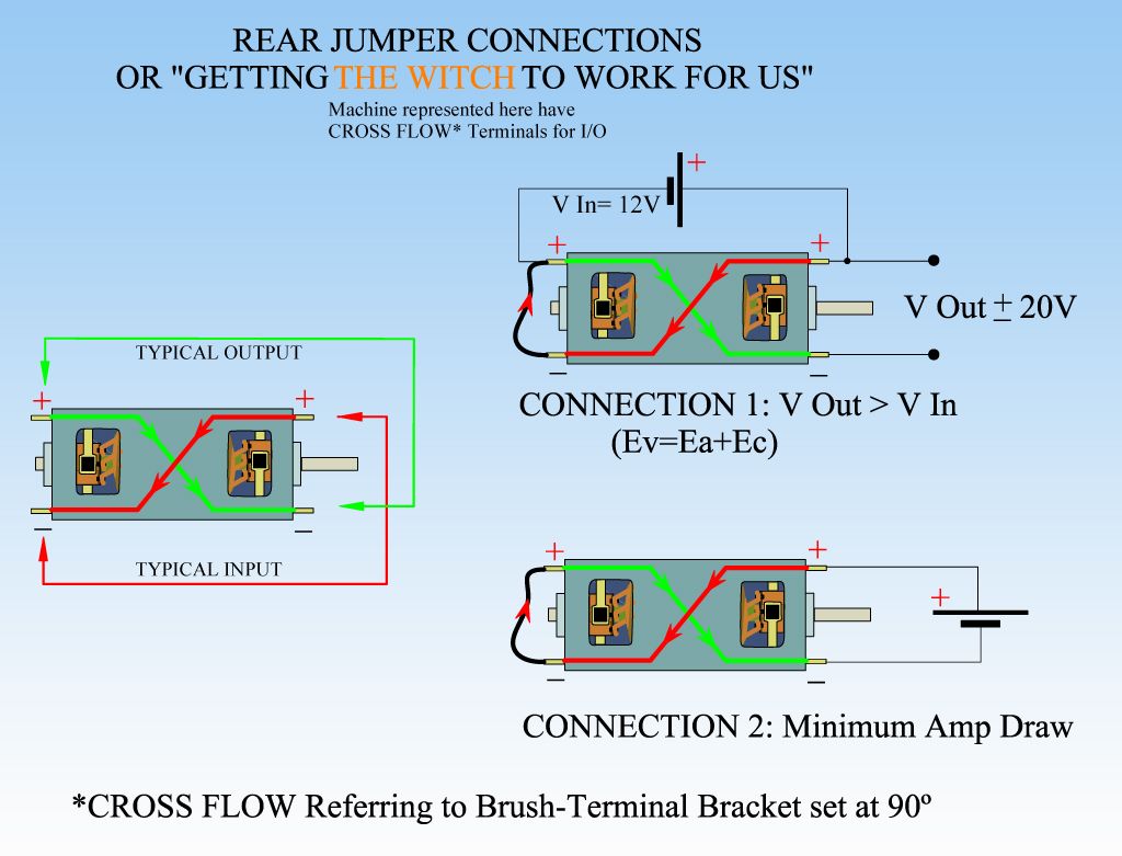
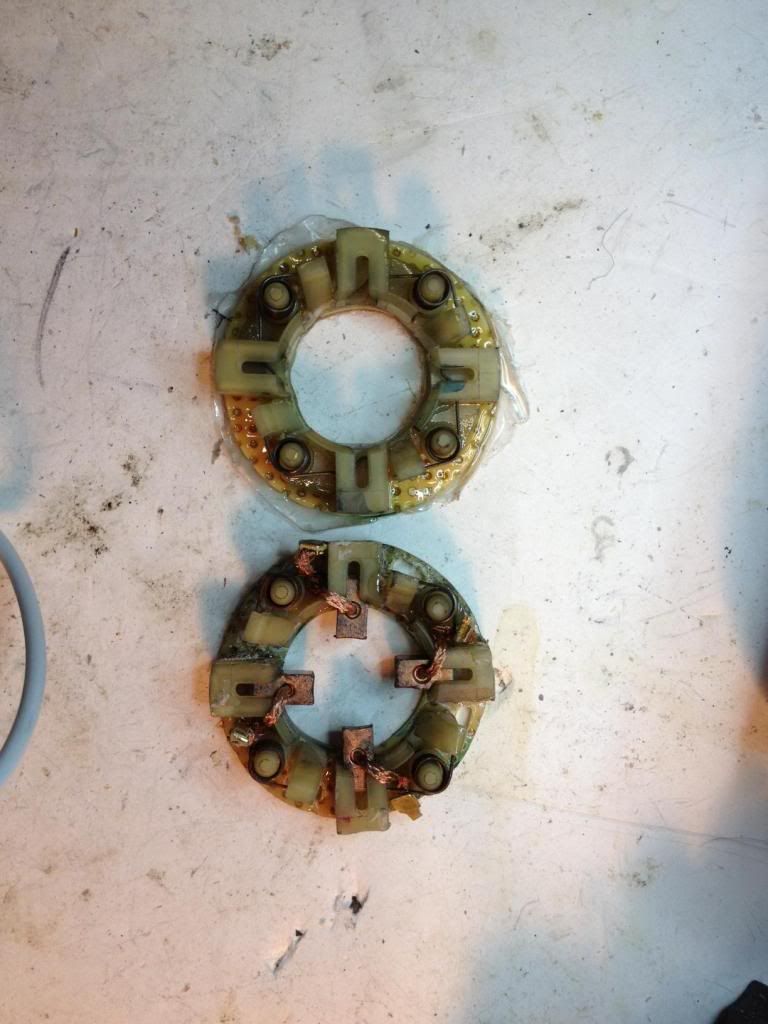
Would it not be a good idea to replace jumpers on comm.? Then
I could get a better comparison with what others have.
Also, did HITBY resolve his low RPM prob?
Appreciate your thots on this, thanx. jw
Howdy UFO, All,
The good news, motor will run, but....
P1 and P8 seem to turn about 2000 rpm if polarity is reversed
and 24v applied. This is with single-segment active on comm.
It wont start with 12v. either pol.
Really surprised at how strongly it 'cogs'. I dont have a pulley
or coupler on the shaft yet. Hard to turn by hand.
P15 and P22 dont seem to work at all. I've found sometimes the
brushes dont make good contact. Ohm-meter shows .3-.4 ohms
comm. to comm. The PMs seem to be right, testing with a cheapo compas.
Would it not be a good idea to replace jumpers on comm.? Then
I could get a better comparison with what others have.
Also, did HITBY resolve his low RPM prob?
Appreciate your thots on this, thanx. jw

 [/IMG]
 [/IMG]
 ?
?


 !!!
!!!
Comment