 Tweet
Tweet
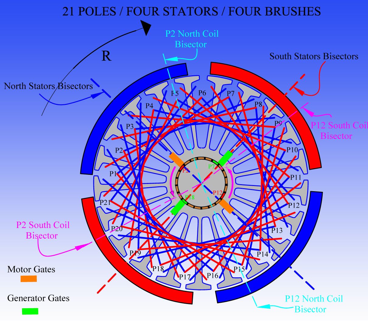
Imp-56 wiring
Howdy UFO, Machine, all,
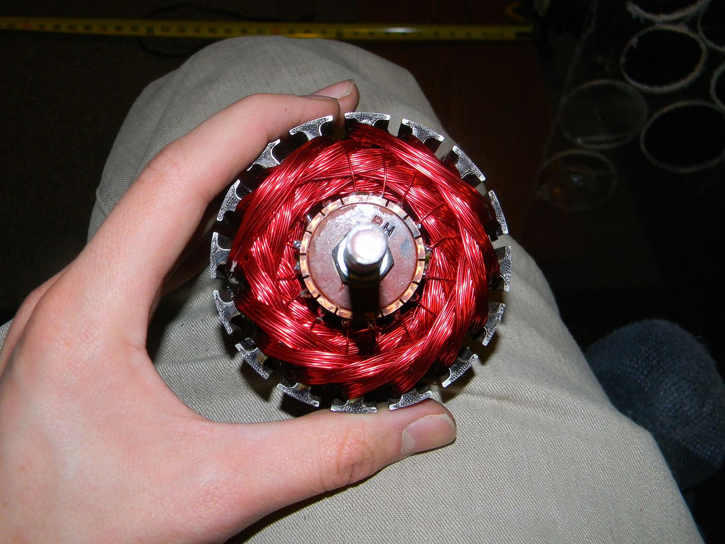
I started wiring armature with 19ga and 17 turns. Wasnt happy with looks,
and probably bad technique, so carefully removed the coils, more-or-less
maintaining coil shape with tape.
Watched the videos again (several times).
I've now wired the first half, P1 thru P14 with 'fresh' wire.
Would it be advisable to straighten as best I can and re-use the wire from the
first attempt? I seem to have plenty of room in the slots, but am wondering
how the ends will be.
Currently the bottom comm is spaced downward to 23mm gap.
If I mill the pedestals that the brush-holder board sits on, it should all clear OK.
Any guidance-comments highly appreciated.
Sincerely, jw39
Howdy UFO, Machine, all,
I started wiring armature with 19ga and 17 turns. Wasnt happy with looks,
and probably bad technique, so carefully removed the coils, more-or-less
maintaining coil shape with tape.
Watched the videos again (several times).
I've now wired the first half, P1 thru P14 with 'fresh' wire.
Would it be advisable to straighten as best I can and re-use the wire from the
first attempt? I seem to have plenty of room in the slots, but am wondering
how the ends will be.
Currently the bottom comm is spaced downward to 23mm gap.
If I mill the pedestals that the brush-holder board sits on, it should all clear OK.
Any guidance-comments highly appreciated.
Sincerely, jw39
 .
.
 [/IMG]


 [/IMG]
Comment