Announcement

Collapse
No announcement yet.

My Asymmetric Electrodynamic Machines

Collapse
X
 
  • Filter
  • Time
  • Show
Clear All
new posts

  • Thanks Gotoloc

    Originally posted by gotoluc View Post
    Congratulations Ufopolitics,

    thank you for making this great video demo.

    You are achieving 1000 Watts of output with only 800 Watts of input.

    You have achieve what Modern Science says is not possible.

    You have my serious attention ... I'm looking forward in your improvement tweaks.
    Please keep this standard test setup in future video as it is very reliable and an easy way to demonstrate efficiency improvements.

    Thank you for freely sharing your research work

    Luc

    Thanks Gotoloc,

    However, I am still not happy with this tests...So I am trying to gather the right measuring equipment/tools/accessories ...to be perfect...As also the "Power of Analysis" enough to analyze very deep all this "scenario"...we have here....So I am not singing "glory" as of yet...till am sure of it all...and can prove it.

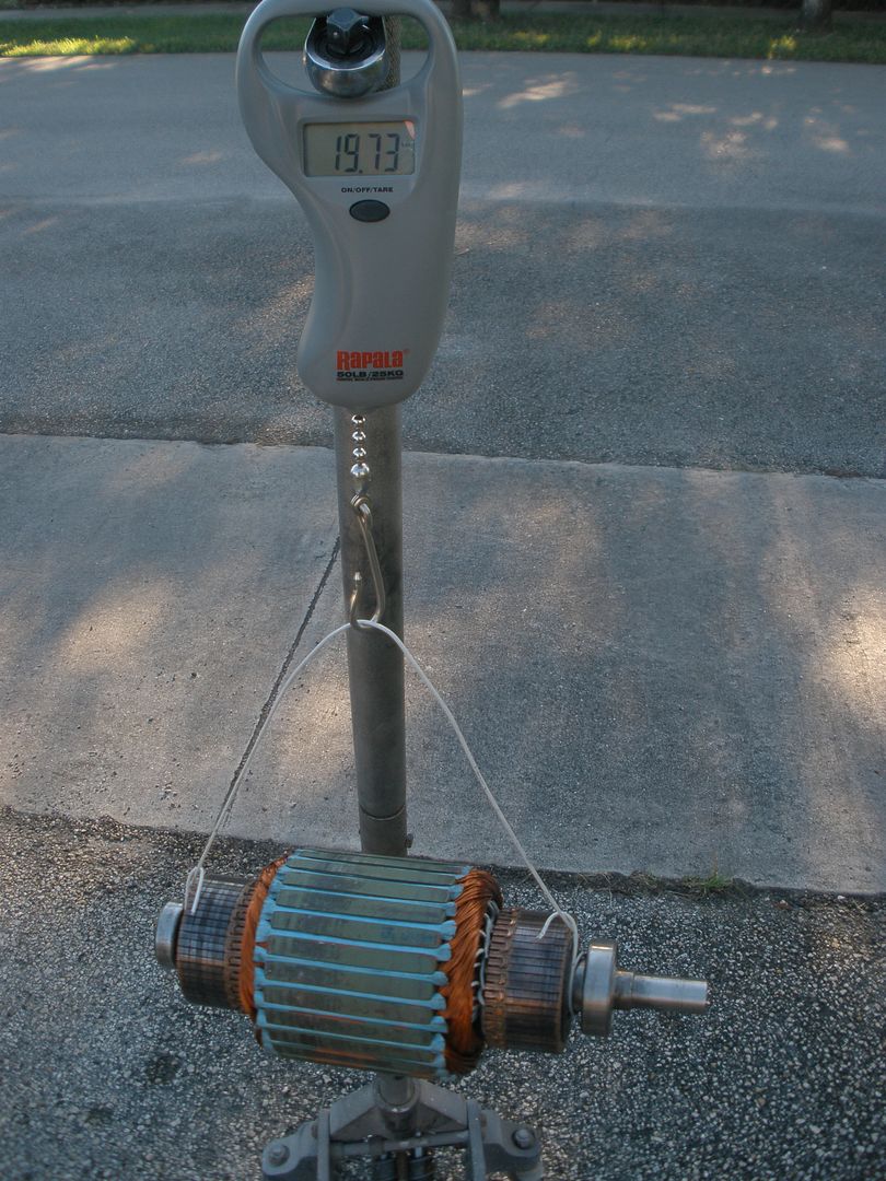
    As also I am arranging the Motor in order that We could play outside in the way we connect brushes between them...as there are many ways to do this, and that Test was done when all connections were in Parallel, so, that obviously made Amps rise too high, since my resistance per coil is too low (0.6 Ohms average)

    But the main issue to consider at Amps reading is to focus in the way My Machines do their connections to Source...and our measurements...

    If We take a closer look, we see that at almost zero time, the circuit is closed...that motor reaches 4500-4600 RPM's/36V...that taken into (Considering only 4400RPM's as the average ) RPS (Revolutions Per Second) would be...73.33 RPS...and we have a 56 Commutator Elements joint every two segments, so there are 28 times hitting that "switch" on-off every 360 degrees/or in angles (360/28=12.86º)...on just ONE Contact when circuit closes...Per Input/Pair/Contact Element...

    Now, If we divide RPS/12.86º...We then get 5.7 Times...that Pair/Coils closes-opens in One Second...while, of course...others 27 go through same procedure...
    And what I mean here is...This Motor is based on an OPEN Circuit System at ALL of its time of Operation taken from just one point-input...based on this Asymmetrical Concept...therefore, a very High Pulsed Motor...
    And as we all know DC Linear Amperage, in order to be measured properly requires a STEADILY CLOSED CIRCUIT, enough time so that DC Amps Measurement Reader could compute those Values properly...and this...does not apply here at any time of its performance.

    If We analyze further the differences between DC Linear Feed...and DC Pulsed Feed...will notice a huge difference...for example:

    Let's take a Popular Component I use on my Oscillators, an N-Channel MOSFET...NTE2397:

    http://www.nteinc.com/specs/2300to2399/pdf/nte2397.pdf

    In first page we will notice this DC FET Component takes LINEAR AMPERAGE only 10 A Max at 25ºC of Temp
    However, at Pulsed Drain Current it can take 40 Amps (at junction Max Temp, which is Junction to Ambient T ...Is 62ºC)

    Now, that IS a huge difference...

    Difference here is 4:1 Ratio in Amps reading...

    And that means, if you add 11 Amps Linear...you will blow this component at 25ºC...while it can take up to 40 Amps Pulsed...at 64ºC...without blowing up...

    Does all this Tell You Something Guys?...

    Again, regards Gotoloc and thanks...but I will keep getting there...

    Some that know me well...know that I won't stop...till you guys see running this two machines without the Batteries...


    Ufopolitics
    Principles for the Development of a Complete Mind: Study the science of art. Study the art of science. Develop your senses- especially learn how to see. Realize that everything connects to everything else.― Leonardo da Vinci

    Comment


    • Thanks Ufopolitics for your great reply.

      So from the looks of it your motor is pulsing the DC (on-off) 2053 times per second.
      I don't think this is too high of a frequency for your DC clamp meter to miscalculate the current. However, nothing beats using a precision shunt and a 2 channel Oscilloscope to get a precision result.

      I'm still happy with the way you did it in your last video.

      If anyone with more experience can point out why the measurements done in UFO's last video would not be acceptable please post your concerns.

      Thanks for your great sharing

      Luc
      Last edited by gotoluc; 12-22-2012, 01:24 AM.

      Comment


      • box weight 28LBs

        DonL
        28 is the correct weight when packed full with bubble wrap.
        Dana
        "Today's scientist have substituted mathematics for experiments and they wander off through equation after equation and eventually build a structure which has no relation to reality."
        Nikola Tesla

        Comment


        • Originally posted by prochiro View Post
          DonL
          28 is the correct weight when packed full with bubble wrap.
          Dana
          Thank you,
          Don

          Comment


          • shipping

            @ Machinealive

            What ever you said to the company has done the trick. The parts were wrapped so well so as to not be recognizable when opening box. Took ten minutes to get it all out. Thank You..... After seeing the bearing holders and thinking, you know what that does, the way the holders are riveted in and the space between them if with just a little modification one could put six or maybe eight holders on one side. If eight the motor case would have an external clamp to hold it togeather. Six looks doable if the outcome would be benificial??? Just adding ideas for the long tern consideration ahead.
            Dana
            Hi Dana,

            I'm glad imperial finally got their act together. Joe seemed genuinely concerned. That's fantastic.

            Cheers

            Comment


            • Hello Lightworker1, Hello to All

              Originally posted by Lightworker1 View Post
              Hello @UFO, @All
              I must admit that until I had that imperial rotor one covered in the green resin, I was was not aware of its mass. I too was until few days ago kind of thinking including some kind of fly-wheel to convert some of the impulse energy into rotational energy to be useful later in the cycle of operation. Well today I went to the UPS STORE and asked to weigh the rotor. The UPS SCALE showed it to be 11.50 lb or 5.21631 kg. As such therefore it already has quite a bit of that fly-wheel effect. If necessary later on more of that fly-wheel effect might be added.
              Now I have to be going out to attend to the necessities life. See you guys later. Good luck.

              Warmest regards
              light
              Hello Lightworker1, Hello to All,

              Light, great, thank You!...We now got the weight of bare armature...

              11.50 lb

              [IMG][/IMG]

              And here I am showing the Total Armature Weight after finished...

              19.73 lb

              All we need now is Commutator Weight, and each bearing weight (remember that front and rear are different size/weight)...then we will have a very close number, on Copper weight...

              Later I will be measuring the Original Armature Total Weight also...

              However, from this Total Weight we could start calculating our Inertia Forces, required to get this huge thing to spin @ 4500 RPM's...as also how much force we need to get it going from a stand still...

              Regards Light, regards to all


              Ufopolitics
              Last edited by Ufopolitics; 12-22-2012, 04:01 PM.
              Principles for the Development of a Complete Mind: Study the science of art. Study the art of science. Develop your senses- especially learn how to see. Realize that everything connects to everything else.― Leonardo da Vinci

              Comment


              • @UFO
                Comm. weight 1 pound 12 OZ. each
                Large bearing 4 OZ
                Small bearing 2 OZ
                Dana
                "Today's scientist have substituted mathematics for experiments and they wander off through equation after equation and eventually build a structure which has no relation to reality."
                Nikola Tesla

                Comment


                • Than You Sir!!

                  Originally posted by prochiro View Post
                  @UFO
                  Comm. weight 1 pound 12 OZ. each
                  Large bearing 4 OZ
                  Small bearing 2 OZ
                  Dana

                  Hello My Dear Friend and thanks much!!

                  We got everything now...

                  See Ya later...

                  Note: Those commutators are HEAVY!!


                  Ufopolitics
                  Principles for the Development of a Complete Mind: Study the science of art. Study the art of science. Develop your senses- especially learn how to see. Realize that everything connects to everything else.― Leonardo da Vinci

                  Comment


                  • Originally posted by dllabarre
                    From the other Thread:


                    I went through the photo bucket and didn't see a schematic of this LM317 modification. I paged back through 30 pages and it's all about the motor.
                    Can you give me an estimated time of when you added this LM317 to the PWM? 2 months ago? 3 months ago?

                    Any help will be greatly appreciated.
                    Thank you,
                    I think this is the link you are looking for:
                    http://www.energeticforum.com/renewa...tml#post184052

                    Comment


                    • Originally posted by prochiro
                      @Donald
                      I was going to show you a schematic of the LM317 circuit from Datasheet but there are other things to learn on this sheet also so just search for national semi LM317 and download the PDF. On it is the diagram and on the right side are your new power inputs to your current circuit. This is a standard diagram and most of us do not put this into you circuit diagrams as it is usually understood. If after you build this, you have questions, just ask.
                      Dana
                      Thank you.
                      I found this one http://www.datasheetcatalog.org/data...r/DS009063.PDF.
                      Has what I was looking for.
                      Greatly appreciated.
                      Last edited by dllabarre; 12-22-2012, 07:24 PM.
                      Don

                      Comment


                      • Originally posted by dllabarre
                        From the other Thread:


                        I went through the photo bucket and didn't see a schematic of this LM317 modification. I paged back through 30 pages and it's all about the motor.
                        Can you give me an estimated time of when you added this LM317 to the PWM? 2 months ago? 3 months ago?

                        Any help will be greatly appreciated.
                        Thank you,
                        Hello Dllabarre,

                        This is from the OTHER Thread...sorry about the confusion...it seems the way I wrote it...

                        [IMG][/IMG]

                        Here it is...already fixed, the one I have previously loaded, had error on resistance values...but error cited on my following post to diagram...I wrote all resistors 2.2K, and one was 220 ohm.

                        Positive Out (12V) is understood goes through the 68 Ohm Resistor to legs 4-8 of IC 555 and also to one leg (not Wiper) of 250K POT...through the 1k Resistor (R8) of Main Diagram below.

                        [IMG][/IMG]

                        And, please, all this data is supposed to be at the other Thread...Controllers, Electronics and Static Coils...make copies of it over there...So I can erase this post from here.

                        Thanks and Regards


                        Ufopolitics
                        Principles for the Development of a Complete Mind: Study the science of art. Study the art of science. Develop your senses- especially learn how to see. Realize that everything connects to everything else.― Leonardo da Vinci

                        Comment


                        • Originally posted by Ufopolitics View Post
                          Hello Lightworker1, Hello to All,

                          Light, great, thank You!...We now got the weight of bare armature...

                          11.50 lb

                          [IMG][/IMG]

                          And here I am showing the Total Armature Weight after finished...

                          19.73 lb


                          All we need now is Commutator Weight, and each bearing weight (remember that front and rear are different size/weight)...then we will have a very close number, on Copper weight...

                          Later I will be measuring the Original Armature Total Weight also...

                          However, from this Total Weight we could start calculating our Inertia Forces, required to get this huge thing to spin @ 4500 RPM's...as also how much force we need to get it going from a stand still...

                          Regards Light, regards to all


                          Ufopolitics

                          Hello UFO thanks for everything.
                          Hope all is going great. Another trip to the UPS Store revealed the following on their scale.

                          Commutator each ------------ 1.70 lb, ---- 0.771107 kg

                          Big Bearing -------------------- 0.25 lb, ---- 0.113398 kg

                          Small Bearing ----------------- 0.15 lb, ---- 0.068039 kg

                          Previous Information

                          Weight of bare armature -- 11.50 lb,---- 5.216312 kg

                          Total UFO Armature Weight after finished... 19.73 lb --- 8.9493775 kg


                          I tried not using my kitchen scale as that one was never calibrated.

                          Next step I am waiting for the new armature replacement and that missing stator assembly. I have also dropped an email to Dyann (who is at present on her vacation)

                          Meanwhile it looks like you are extremely busy with the R&D at The UFO Corp.

                          We are highly appreciative of all your great efforts.

                          Here I am about to start winding the 5 coils on my goldmine motor after aligning the two commutators. Hope to finish that one soon.

                          Warmest regards
                          light
                          Last edited by Lightworker1; 12-23-2012, 05:11 AM. Reason: typo

                          Comment


                          • Hello UFO, everyone

                            You need a coupler, 3/4" motor side 7/8" gen side.
                            Motor needs to be shimed up about .47",
                            internal mag dia 4.75".

                            UFO, old buddy, old pal, if you still have your motor apart, could you measure distance from ends of rotor, to comms, that would save some time, thanks.

                            Comment


                            • Machine...

                              Originally posted by machinealive View Post
                              Hello UFO, everyone

                              You need a coupler, 3/4" motor side 7/8" gen side.
                              Motor needs to be shimed up about .47",
                              internal mag dia 4.75".

                              UFO, old buddy, old pal, if you still have your motor apart, could you measure distance from ends of rotor, to comms, that would save some time, thanks.
                              Hello Machine,

                              I still have it apart, because I am adding (and making) the red positive cables separated, so I can joint them outside...using same black ones that bring as negatives...
                              The distance?...What distance?...idk!!...

                              Machine, remember I had Motor assembled when I got them, so commutator was on already (original)...therefore, I pressed second commutator according to that distance...PLUS like 3-4 mm more apart from rotor...meaning My Upper Commutator seats @ 21 mm, since Original Commutator comes at 18 mm distance.
                              So, from factory Commutator bottom surface to upper rotor surface is @ 18 mm (and here, my friend, that measurement depends on epoxy coating thickness you have...and...they are not all the same)...so,it could be off a bit and it be better to be more than 18 mm...say 19 mm, NO LESS!! your perfect adjustment (final) would be after setting outer rear bearing on (the smaller one on to shaft)...then setting the Rotor with commutator and rear bearing at the rear end housing-with the Brush Board on (better take brushes off to do this operation...or just push them back till spring hold them from coming in)...
                              Now right there, check based on brush board and brush Housings (all Four) The HEIGHT...IF THEY ALIGN IN HEIGHT WITH COMMUTATOR AREA TO BE SWEPT/BRUSHED PERFECT...then they are fine...

                              You can do same operation for other Commutator mounting...and there is space to play with, between bearing to commutators...so don't worry.

                              Is better you keep them trying not to pass pressing IN...this numbers I gave you...just because pulling requires a Puller... ...I have used a Steering wheel pulley...but a gear pulley could also be used as a bearing extractor... BUT that is a "risky" operation, rather than softly smoothly press IN...You know it...

                              Some cases , the splines to lock rotor laminations...that are all the way up to commutators are too high...so I file them a bit...more likely... till half way of commutator width...at shaft...to allow a smooth pressing...

                              Regards


                              Ufopolitics
                              Principles for the Development of a Complete Mind: Study the science of art. Study the art of science. Develop your senses- especially learn how to see. Realize that everything connects to everything else.― Leonardo da Vinci

                              Comment


                              • Thanks UFO,

                                If I can aviod using the gear pullers, and only press once, I would be happy . I can use washers to shim brush plate, if I have to.


                                machine

                                Comment

                                Working...
                                X