Announcement

Collapse
No announcement yet.

My Asymmetric Electrodynamic Machines

Collapse
X
 
  • Filter
  • Time
  • Show
Clear All
new posts

  • 10 Pole windings

    Ian,
    I hope this is wrong because I finished winding a 10 pole motor yesterday.
    I have not finished the holding part for the magnets and housing, so
    I have no test results yet. I want to be able to rotate the magnets to
    adjust the timing. It makes more sence on this motor to do it this way. I am tring to upload pictures to photobucket but it's not responding. So I will post pictures later.
    I wraped three pole at a time, and all my wraps went CCW while looking
    at the rotor with the positive end up. Hope that is clear, but my pictures will show it.


    Originally posted by iankoglin View Post
    G'day UFO
    I today picked up my Windscreen motor/s modified by my local friend Andrew

    I have some pics here
    Windscreenmotor_mod pictures by Kogs1 - Photobucket
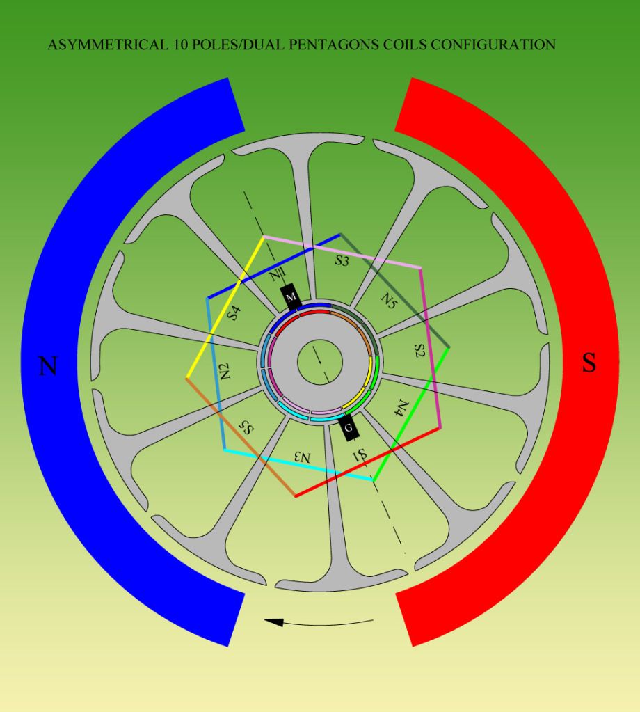
    You suggested some time ago that the Double pentagon would be Ideal for this motor


    AS I understand there are 5 pairs of windings that are set parrallel to each other like N1 and S1 being one single winding Just wound similar to the RS 5pole motor instead of a Vee they are parallel.

    The 2 windings on the original motor were 30.5mtrs each the thickness is 0.7mm diam and measuring 1.84 ohms
    I did not unwind the wire so I do not know exactly how it was wound

    As 2 windings
    Please should I use the same size wire as I think would need to have more length to have the 1 Ohm per pair of coils
    or
    Use reduce wire thickness to be able to fit comfortable the wire measuring 1 Ohm

    I have .8mm wire but I am sure that would not fit so I will have to purchase new wire

    Kindest regards


    Ready to wind up

    Comment


    • Dyno Tests II Part...

      Originally posted by Turion
      UFO,
      Did you have a chance to look at the torque test I posted above for the standard motor?

      Standard Motor Torque Test - YouTube

      Is that a fair test? If so, I will run it on the converted motor, but before I do, some questions..

      1. Should I run it at 12 volt, 24, 36, or what, to get a fair test. I could redo the test on the standard motor at that higher voltage. It's a 24 volt motor, but it might handle 36 for a few seconds of testing.

      2. should I have a load on the modified motor generator side while I run the torque test? I know you have said to have a load on it for other tests.

      Just want to make sure I get everything right before I run tests and film it.

      EDIT: Never mind. I just realized why that is wrong. I will work on something better. (It helps to have friends like Matt who points out the stupid mistakes I make) LOL

      Dave
      Hello Dave,

      I responded by the time I saw this...but I will add...

      1. Should I run it at 12 volt, 24, 36, or what, to get a fair test. I could redo the test on the standard motor at that higher voltage. It's a 24 volt motor, but it might handle 36 for a few seconds of testing.
      You are testing Original Spec's versus Modified Spec's right?...

      So it would be expected that Original is taken to its factory recommended Input (I already wrote about this prior)...which is...

      24 Volts and 13.5 - 15 Amps


      Therefore, that is the power you will be applying to BOTH Motors, well, the original is just "A Motor" mine is "A Machine"...or an "Engine"...

      Now, the whole idea here is that either Original accomplish its factory spec's...and you will apply certain mechanical force to take it to a STOP...while reading ALL Parameters...

      Then you do exactly to My Machine...to see if at Stop Momentum Parameters are the same, below or above...

      Important Note: That "Stop Momentum" must be as short as possible, otherwise you will have fire and smoke there, basically on Original.

      Edit: Now related to adding a Load to my Machine Output...I will say this...
      If You will be testing Torque on two given Gas Engines...One the Exhaust Tube is designed to blow right back at your Input, just like a Turbo-Booster...but the other Engine have a completely independent Exhaust System...Now, will you close that exhaust to make the testings?...No right?...then do apply a load to My Machine (and that load must be balanced with Input)...otherwise it will read Mega Amps...and there will be no meter that could measure that...


      Regards


      Ufopolitics


      PD: I see you are being "assisted" by Mathew Jones...but in the "background"...just like a "Secret Counselor"?...
      That's great.
      Last edited by Ufopolitics; 08-17-2012, 09:04 PM.
      Principles for the Development of a Complete Mind: Study the science of art. Study the art of science. Develop your senses- especially learn how to see. Realize that everything connects to everything else.― Leonardo da Vinci

      Comment


      • Torque related info:

        When you have some 12 minutes to spare for watching this youtube video from about minute 3:50 then you could see Peter Lindemann's practical demo on measuring motor torque, you may find it also informative and practical. Lasts about 12.5 minutes:
        Peter Lindemann -- Electric Motor Secrets - YouTube

        Those that have not purchased this video from Peter can do so here:
        Electric Motor Secrets by Peter Lindemann
        It is well worth the cost and supports Peter's research to bring us more valuable information. Peter has gone to great lengths to standardize torque measurement so we can all be on the same page. Please stay away from shortcuts that will leave out some of the key variables.

        If we all follow Peter's method for measuring torque, we will all be on the same page when comparing/discussing results of many upcoming Ufopolitic's motor conversions. This would be the fairest methodology to follow as it includes the underlying key variables for comparing apples to apples.

        Force, Acceleration, & Torque
        These "reaction" sensors measure the torque that is transferred by the shaft to the restraining elements. The resultant reading is not completely accurate, as it disregards the inertia of the motor. (Similar method/setup to what DadHav/Turion are doing/proposing, if this statement is incorrect, it will be removed).

        Other resources for measuring torque:

        Ideally, this type of device would be most accurate but cost prohibitive:
        Rotating Torque Sensor, Shaft to Shaft Configuration
        Rotating Torque Sensor, Shaft to Shaft Configuration

        http://www.hastings.edu/downloads/DEasterly.pdf
        Design, Fabrication, and Testing of a Small Engine Dynamometer

        Alternator conjecture is false
        Moment arm set up is Legitimate

        http://www.stirlingengine.com/downlo...ing_manual.pdf
        See Page 19 for a simple torque measurement in the PDF file

        Prony brake - Heretical Builders
        Pony break construction

        IndianaBoys
        Last edited by IndianaBoys; 08-17-2012, 09:08 PM.

        Comment


        • A thousand words

          Here are the Pictures of the little 10 Pole and also a couple other's.

          Asymmetrical 10 Pole Motor pictures by AMP2000 - Photobucket

          UFO, The one 16 pole 32 comutator is a very nice built motor and will be able
          to be rewound if I can use it as a motor.. Otherwise it could make a nice generator..

          Mark


          Originally posted by Rl2003 View Post
          Ian,
          I hope this is wrong because I finished winding a 10 pole motor yesterday.
          I have not finished the holding part for the magnets and housing, so
          I have no test results yet. I want to be able to rotate the magnets to
          adjust the timing. It makes more sence on this motor to do it this way. I am tring to upload pictures to photobucket but it's not responding. So I will post pictures later.
          I wraped three pole at a time, and all my wraps went CCW while looking
          at the rotor with the positive end up. Hope that is clear, but my pictures will show it.

          Comment


          • Over Unity Wrong and Right Concepts...

            Hello to All,

            I thought I must write here the real concepts of the so simple word...Over Unity...

            In "Plain Math" Over Unity means "Over One"...meaning, anything that in a simple given equation of Unity (1/1 or One over One) the upper number exceeds the lower number...That is Over Unity.
            And no matter if it is 1.00001/ 1.0 it is still OU.
            Clear so far?

            Ok so let's proceed now to the same application, but given to a Machine, a Motor in this case...

            A Motor is a machine designed to transform an Input of Electrical Energy and Convert it to A Mechanical Force...right?

            Right, so, any given Motor that we all could measure its Input...and its Output (Mechanical)..we can then put those values in our "Unity Equation" that we all learned from Second Grade at Primary School...I believe?

            So for any given Motor

            Motor Unity Formula= OUTPUT/INPUT

            And this is why, our Physics says...there could not be a Over Unity Motor...just because no matter how much mechanical output any motor outputs...that Number that goes "above" in the equation...will never be EVEN EQUAL, much less Higher than bottom number....So below is a very "easy" to understand example:

            Motor Unity Formula= Output/Input= 1/2 (example)=0.5<1.0

            But the problem is...that in order to take this values to the Unity Equation...We MUST take them into equally and previously conceived parameters, so they "MATCH" each others in the same given "weights"...so we have to convert them in the required "fashion"...
            Meaning, we can not just throw Volts over Pounds and expect an accurate result?...Or Amps over RPM...Or Watts over Grams...right?

            That is why we went to our beautiful schools...to learn all that...and if we have "any doubts" then we are free to consult-refer to other methods-videos-people, and review their scientific approaches to be able to do our testings and compare results the way is written...for so long.

            Now when taking Electrical Values to a "Single Unit" in order to be compared in our beautiful "Unity Formula"...we must get Volts and Amps...and multiply them to obtain a unique measure we must know right?...and that value is >>>Watts

            So we have a "Battery"...and a Battery only can "give out" what it has stored...as its Max Capacity...otherwise, we will kill it instantly...if demanding more than its capacity...so Input is very easy to calculate since Battery spec's are on its Label...However a given Motor may not need as much power to run at "IDLE"...However, when we add a mechanical load...it increases its Amperage Draw...so we must keep reading and writing those spec's (Voltage-Amps) when testing a Motor for "Unity Formula"

            When referring to My Specific Machines being Disclosed here... and trying to evaluate them in our "Unity Equation"...We MUST consider that those Machines, besides a SIMPLE MOTOR that I previously explained above...that "just" converts Electricity to a Mechanical Force...BUT, My Machines are Capable to "also" deliver a POSITIVE "Electrical Output"...

            Now when we come to our Unity Equation...we MUST consider that Electrical Output, whatever it measures...no matter if it is 0.001 Volt/0.001 Amp...We MUST add it to the Mechanical Output or "Number Above" in Our Unity Equation nice Formula...

            Therefore we have:


            UFO MACHINE UNITY FORMULA = MECHANICAL OUTPUT + ELECTRICAL OUTPUT / ELECTRICAL INPUT


            Simple right?

            So please, knowing that just that very small Radio Shack Motor...Outputs Positive Electrical Values between +- 8.0 to 9.0 Volts, when applying 10 Volts (Input)...plus its "INCREDIBLE TORQUE" more than Original...Then, to "Any Average Mind" it will be clearly understood...it IS An Over Unity Machine AS IS, just by looking at those simple facts.

            So this was written for further Testings to come...to be done in a FAIR WAY, like I am writing here, just exactly as this...I AM VERY POSITIVE, AND SO SURE, My Machines will BLOW OUT ANY ORIGINAL MOTOR MECHANICAL OUTPUT FORCE (TORQUE)...However...I MUST INSIST We ALSO ADD its POSITIVE ELECTRICAL OUTPUT in our very simple formula of "Unity"...
            As for many others that just "throw words in the air" without even knowing what they are talking about...


            Thanks for reading this, and I am sorry for its length, but I needed to clarify this at some point here.

            Regards


            Ufopolitics
            Last edited by Ufopolitics; 08-17-2012, 10:30 PM.
            Principles for the Development of a Complete Mind: Study the science of art. Study the art of science. Develop your senses- especially learn how to see. Realize that everything connects to everything else.― Leonardo da Vinci

            Comment


            • Wrong Turion..

              Originally posted by Turion
              Horsepower test - YouTube

              If this looks good, I will have my wife read the tach while I video all the other readings at the same time. But that will have to be tomorrow. Going out to a big deal dinner tonight and have to get cleaned up to go.

              Dave
              Hello Dave,

              Man, I am really sorry to be "objecting" here to you...honestly I do, because I see how much work you are doing trying to satisfy our requirements...as we seat our AS**S watching you do the work...not fair.

              But Dave, setting steady weights there is not the point...that Force is supposed to be applied by you, manually...while you take the Input of Motor to a known Steady Amp Value...Peter applied that force while watching Current (I) to climb to Seven (7.0) Amps in his Power Source...Voltage is not going to increase in this measurement of force-tension applied to shaft...but Amps will.

              You must take that Original Motor at its Max Spec's of Input, and so Mine...Which is 13.5 to 15 Amps at 24 Volts Input....So you have to manually pull that Original Motor to "spend" exactly 15 Amps...by applying YOUR VARIABLE PULLING FORCE Through the scales to the wheel-Shaft of Both Machines.

              Again, You have to apply a variable force (Mechanical Load) to get to 15 Amps/24V ...then in that instant read Pounds at Scales and also RPM's at that exact time.

              Now In My Machine case:

              1- It MAY reach that Amp Value before Original and not getting to deliver the same WEIGHT at Scales Value ...therefore, it will be UNEVEN tests, so even if you KEEP GOING, keep pushing...Applying more pressure...you will reach that weight number by the time very High Amps will be shown in your meters...To remedy that, you MUST add a Load at Output, and READ THEM, in Amps-Volts , A load like 5 CFL's or more of 23 Watts in Parallel ...That will decrease its Amp Draw from showing at Input...PLUS, You will ADD those Output Electrical Values to My Machine Total Mechanical Output...please do not forget that...

              That is the Point Here.

              The next Test will be to take both Machines to an almost STOP ...while measuring parameters...mainly WEIGHT at Scales. This will be to know how far and how much Power they could go as a Max Limit.

              Now the wheel, I remind You is Circumference not Diameter...meaning wrapping a tape measure around wheel, (exactly where belt will be turning, not outer rim) should close at exactly 12 inches.


              Regards


              Ufopolitics
              Last edited by Ufopolitics; 08-17-2012, 11:45 PM.
              Principles for the Development of a Complete Mind: Study the science of art. Study the art of science. Develop your senses- especially learn how to see. Realize that everything connects to everything else.― Leonardo da Vinci

              Comment


              • Great Pic's!!

                Originally posted by Rl2003 View Post
                Here are the Pictures of the little 10 Pole and also a couple other's.

                Asymmetrical 10 Pole Motor pictures by AMP2000 - Photobucket

                UFO, The one 16 pole 32 comutator is a very nice built motor and will be able
                to be rewound if I can use it as a motor.. Otherwise it could make a nice generator..

                Mark

                Hello Mark,

                Great pic's !!...Now, please take off, all those electronic components at brushes housings...like the Inductors and Ceramic Caps...they were there to capture B EMF...We do not have it now... ...therefore we don't need them...

                That 16 Poles could be a good Motor...will you be able to get a Comm for it?...If you could get a smaller diameter and 16 Poles will be excellent...if not just joining two elements will do...


                Regards


                Ufopolitics
                Principles for the Development of a Complete Mind: Study the science of art. Study the art of science. Develop your senses- especially learn how to see. Realize that everything connects to everything else.― Leonardo da Vinci

                Comment


                • Now the wheel, I remind You is Circumference not Diameter...meaning wrapping a tape measure around wheel,
                  (exactly where belt will be turning, not outer rim) should close at exactly 12 feet.
                  Regards
                  Ufopolitics[/QUOTE]

                  I beleive he means 12 inch's, but this is understandable with all you are doing
                  UFO..

                  Thanks for the time you are putting in here.
                  Mark

                  Comment


                  • NO Electronics

                    Yes, I will remove the electronics from them, and give it a run.
                    The 16 pole motor is a beautiful motor, but I will need to look around to see if
                    I may find a 16 element commontator. The brushes however are very wide and do reach
                    across two of the commentators. So I beleive it should be ok.
                    Mark


                    Originally posted by Ufopolitics View Post
                    Hello Mark,

                    Great pic's !!...Now, please take off, all those electronic components at brushes housings...like the Inductors and Ceramic Caps...they were there to capture B EMF...We do not have it now... ...therefore we don't need them...

                    That 16 Poles could be a good Motor...will you be able to get a Comm for it?...If you could get a smaller diameter and 16 Poles will be excellent...if not just joining two elements will do...


                    Regards


                    Ufopolitics

                    Comment


                    • Ufopolitics,

                      While on the subject of Over Unity:

                      Back in 2007, Stefan Hartmann the owner of the OverUnity.com Forum has put together prize money for anyone developing an open source Over Unity device. To date, no one has claimed the prize. It has reached a value over $15,000 US for any device that meets the below requirements.

                      Stefan has stated the requirements at:
                      OverUnity Prize conditions for 1 Watt Device
                      OverUnity Prize conditions for 1 Watt Device PDF file attached

                      IndianaBoys

                      Comment


                      • Originally posted by Turion
                        Horsepower test - YouTube

                        If this looks good, I will have my wife read the tach while I video all the other readings at the same time. But that will have to be tomorrow. Going out to a big deal dinner tonight and have to get cleaned up to go.

                        Dave
                        Turion,

                        Your set up is coming along nice.

                        You could replace the weights with cable tensioner's (Home Depot) or something similar and I believe you are there. You can dial the tension in to various levels and get your readings. As per Peter's video, the tension on 1 scale is to read ZERO.


                        Thank you for going into action and sharing your work!

                        IndianaBoys
                        Last edited by IndianaBoys; 08-18-2012, 01:12 AM.

                        Comment


                        • Predicting the &quot;Future&quot;...

                          Originally posted by Turion
                          UFO,

                          I got this from Wikipedia:
                          Pony brake
                          In its simplest form an engine is connected to a rotating drum by means of an output shaft. A friction band is wrapped around half the drum's circumference and each end attached to a separate spring balance. A substantial pre-load is then applied to the ends of the band, so that each spring balance has an initial and identical reading. When the engine is running the frictional force between the drum and the band will increase the force reading on one balance and decrease it on the other. The difference between the two readings is used to calculate torque, because the radius of the driven drum is known. If the engine speed is measured with a tachometer, the brake horsepower is easily calculated. The circumference of my wheel is exactly six inches or 1/2 a foot. I had to make it that small , not because of the standard motor, but because that's all the clearance I have on the modified motor between shaft and bench top, and I need to be able to measure THAT motor too.
                          No errors. Five pounds of weight is five pounds of weight. That's why I chose this method. Is that ok? I would still measure amps and volts, because the system is under load, and then take a measurement without it being under load so yo have a difference if you need it.

                          Dave

                          Ok Turion,

                          So You are gonna do this test, according to some "Wikipedia" Professional Dynamometer Counseling"

                          ...and not based on Peter Lindemann Video?...so, that sound great, very!

                          I can tell you exactly what would be your final conclusions, based on your readings...And No, I am not a "Spiritual Reader" and I do not have a "Crystal Ball"...


                          Ok...

                          So, let me keep "guessing"...you are gonna try first the Original Motor , even though it really do not matters...same thing..

                          That Motor is gonna be "suffering" at those weight values?... NOT at all, it is gonna be very "relaxed" ...so it is gonna show a very low Amp Draw...

                          So then You are gonna proceed to test the Modified Motor...

                          And (of course) the same exact small weights (To be Fair right)...then my Machine is gonna show a huge amount of Amp Draw...


                          So the conclusion would be very simple...

                          UFO Machine requires 10X Amps to take X Pounds of force...While Original only spends 1X Amps taking exactly same X Pounds of Torque...


                          Yeah right, And then I was born yesterday...in the morning...!!!....


                          Was that Matt who told you to do that?....

                          I told You before, I wanted You to apply exactly FULL LINEAR POWER to the ORIGINAL Motor...Then SAME EXACT Input to Mine...While trying TO STOP/STALL BOTH MACHINES ...NOW...WILL YOU DO THAT?!

                          After you do that I really could not care less how many Amps NEITHER Machine showed...really!

                          And I am just trying to avoid here another Bombardment against My Machines, because of ANOTHER WRONG TESTING...like the one YOU did before...taking both Machines at same RPM's , Lowering the Voltage to mine, then reading Amps...??!!

                          That is all I am trying to avoid...


                          UFO
                          Last edited by Ufopolitics; 08-18-2012, 03:58 AM.
                          Principles for the Development of a Complete Mind: Study the science of art. Study the art of science. Develop your senses- especially learn how to see. Realize that everything connects to everything else.― Leonardo da Vinci

                          Comment


                          • I Started This Thread...

                            Hello To ALL,

                            I Want to make sure WE Understand Each Others, on this very POST.

                            This is MY THREAD, HERE I am disclosing MY MACHINES, MY DESIGNS, AND MY CONCEPTS...As I am helping in all ways-forms FOR YOU GUYS to replicate them as I have been doing as up to NOW.


                            BUT:


                            NOW WHEN IT COMES TO TESTING MY MACHINES , MY DESIGN IN ORDER TO COMPARE THEM, CRITICIZE THEM, ANALYZE THEM OR WHATEVER...I RESERVE ENTIRELY THE RIGHT TO APPROVE OR NOT TO APPROVE ANY OF THOSE TESTINGS, IF THEY ARE NOT DONE, MADE OR EFFECTED ACCORDING TO MY SPECIFICATIONS, MY EXPLANATIONS AND MY FINAL DECISIONS.

                            It is understood that the Replications you have made are yours /AS PERSONAL PROPERTY ON PARTS-LABOR/ BUT THE MAIN IDEA IS MINE, AND THE REASON THEY ARE "ALIVE AND RUNNING"...Therefore, I UNDERSTAND YOU HAVE THE RIGHT TO CONDUCT ANY TESTING YOU PLEASE ON YOUR SIDE...THAT IS "YOUR PREROGATIVE"...HOWEVER, THAT DOES NOT MEAN IS "MY PREROGATIVE" TO "ACCEPT THEM".

                            So, You Guys could do absolutely WHATEVER YOU LIKE...

                            FINALLY...I decide if "APPROVED" or "NOT APPROVED"...


                            CAPISCI?


                            UFOPOLITICS
                            Last edited by Ufopolitics; 08-18-2012, 03:43 AM.
                            Principles for the Development of a Complete Mind: Study the science of art. Study the art of science. Develop your senses- especially learn how to see. Realize that everything connects to everything else.― Leonardo da Vinci

                            Comment


                            • De Prony Test...Not &quot;Pony&quot;

                              Text taken from "Wikipedia":

                              The de Prony Brake is a simple device invented by Gaspard de Prony to measure the torque produced by an engine. The term "brake horsepower" is one measurement of power derived from this method of measuring torque. (Power is calculated by multiplying torque times rotational speed.)
                              Brake horsepower (bhp) is the measure of an engine's horsepower before the loss in power caused by the gearbox, alternator, differential, water pump, and other auxiliary components such as power steering pump, muffled exhaust system, etc. Brake refers to a device which was used to load an engine and hold it at a desired RPM. During testing, the output torque and rotational speed were measured to determine the brake horsepower. Horsepower was originally measured and calculated by use of the "indicator" (a James Watt invention of the late 18th century), and later by means of a De Prony brake connected to the engine's output shaft. More recently, an engine dynamometer is used instead of a De Prony brake.

                              FOR THOSE THAT HAVE "NO IDEA" ...AN ENGINE REFERS TO A GAS OR DIESEL ENGINE...NOT AN ELECTRIC MOTOR


                              Engine dynamometer

                              An engine dynamometer measures power and torque directly from the engine's crankshaft (or flywheel), when the engine is removed from the vehicle. These dynos do not account for power losses in the drivetrain, such as the gearbox, transmission, and differential.
                              Electric motor/generator dynamometer

                              Electric motor/generator dynamometers are a specialized type of adjustable-speed drive. The absorption/driver unit can be either an alternating current (AC) motor or a direct current (DC) motor. Either an AC motor or a DC motor can operate as a generator that is driven by the unit under test or a motor that drives the unit under test.
                              Electric motor/generator dynamometers are generally more costly and complex than other types of dynamometers.

                              The "Inventor":

                              Gaspard Clair François Marie Riche de Prony (July 22, 1755 - July 29, 1839) was a French mathematician and engineer, who worked on hydraulics. He was born at Chamelet, Beaujolais, France[1] and died in Asnières-sur-Seine, France.

                              BEING ON THE TWENTY FIRST CENTURY...SOMEONE COULD TELL ME WHY DO WE NEED TO USE A "TECHNIQUE" FROM THE 1800'S TO MEASURE TORQUE IN STATE OF THE ART REVOLUTIONARY MACHINES??!!


                              UFOPOLITICS
                              Last edited by Ufopolitics; 08-18-2012, 04:32 AM.
                              Principles for the Development of a Complete Mind: Study the science of art. Study the art of science. Develop your senses- especially learn how to see. Realize that everything connects to everything else.― Leonardo da Vinci

                              Comment


                              • Hello Ian...

                                Originally posted by iankoglin View Post
                                G'day UFO
                                I today picked up my Windscreen motor/s modified by my local friend Andrew

                                I have some pics here
                                Windscreenmotor_mod pictures by Kogs1 - Photobucket
                                You suggested some time ago that the Double pentagon would be Ideal for this motor


                                AS I understand there are 5 pairs of windings that are set parrallel to each other like N1 and S1 being one single winding Just wound similar to the RS 5pole motor instead of a Vee they are parallel.

                                The 2 windings on the original motor were 30.5mtrs each the thickness is 0.7mm diam and measuring 1.84 ohms
                                I did not unwind the wire so I do not know exactly how it was wound

                                As 2 windings
                                Please should I use the same size wire as I think would need to have more length to have the 1 Ohm per pair of coils
                                or
                                Use reduce wire thickness to be able to fit comfortable the wire measuring 1 Ohm

                                I have .8mm wire but I am sure that would not fit so I will have to purchase new wire

                                Kindest regards


                                Ready to wind up

                                Hello Ian,

                                I am sorry I could not answer before...but Ok...

                                AS I understand there are 5 pairs of windings that are set parrallel to each other like N1 and S1 being one single winding Just wound similar to the RS 5pole motor instead of a Vee they are parallel.
                                That is correct Ian, is just like winding one single coil, except "jumping" in the middle to the other side...here are "No Turns" like in the "V" Shape of R/S...

                                Please should I use the same size wire as I think would need to have more length to have the 1 Ohm per pair of coils
                                or
                                Use reduce wire thickness to be able to fit comfortable the wire measuring 1 Ohm

                                I have .8mm wire but I am sure that would not fit so I will have to purchase new wire
                                Ian the One Ohm is basically a "Minimum Restriction", but it could go higher, no problems there...of course not so high that it will not turn...

                                Do not get too thin wire though...

                                Please Ian, pay very close attention to the way Brushes Alignment is set related to Stators, note the intermittent line. However You could move them within certain angle...but more to right than to left...to gain force-speed.
                                Please note the Color Codes on Commutator Elements matching the Color of Pairs...

                                Those are very important issues for motor to run properly.


                                Warm Regards


                                Ufopolitics
                                Last edited by Ufopolitics; 08-18-2012, 04:30 AM.
                                Principles for the Development of a Complete Mind: Study the science of art. Study the art of science. Develop your senses- especially learn how to see. Realize that everything connects to everything else.― Leonardo da Vinci

                                Comment

                                Working...
                                X