 Tweet
Tweet
Generator Output
Hi Guys,
I would like to confirm my observations with the generator output of the asymmetric motor. While powering the motor through the input connection, any load I connect to the output generator connections causes an increase in current draw from my source 12v battery. Has anyone else noticed this?
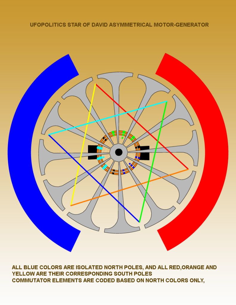
Btw, I'm getting around 6v on the generator output and 18 volts when using the jumper across the motor input and generator output(As shown by UFO). I was under the impression that the generator output was isolated from the input. If its not isolated what is the benefit of the generator output while running the motor?
Keep in mind, I have not run any tests running the asymmetric motor solely as a generator, just in the motor/generator mode. Hopefully Turion will have some data soon on the generator side of things.
In any case, this is just the observation of a novice. I just want to confirm if I'm off track or if my findings are consistent with others who have completed the replication.
Thank you
Hi Guys,
I would like to confirm my observations with the generator output of the asymmetric motor. While powering the motor through the input connection, any load I connect to the output generator connections causes an increase in current draw from my source 12v battery. Has anyone else noticed this?
Btw, I'm getting around 6v on the generator output and 18 volts when using the jumper across the motor input and generator output(As shown by UFO). I was under the impression that the generator output was isolated from the input. If its not isolated what is the benefit of the generator output while running the motor?
Keep in mind, I have not run any tests running the asymmetric motor solely as a generator, just in the motor/generator mode. Hopefully Turion will have some data soon on the generator side of things.
In any case, this is just the observation of a novice. I just want to confirm if I'm off track or if my findings are consistent with others who have completed the replication.
Thank you
 [/IMG]


 that "at least" it runs better than before...when it was a cooking range, and Oil, water -Gas leakier..and tended to overheat every quarter mile...stall and leave you in the middle of the road...
Comment