 Tweet
Tweet
Ufo
o.k I think I understand what you are saying -
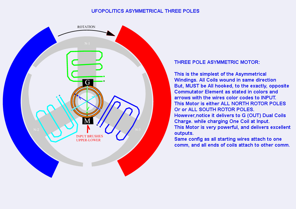
1/ That when the respective motor coil leaves the contact of brush it is charged like a capacitor and then discharges at the delivery side 180 degrees apart.
Wouldn't the speed of the rotor be of importance? because the coil would only hold that charge for a certain amount of time, the faster the better to get as much charge to delivery brushes as quick as possible.
2/ I thought that the brushes 180 degrees apart were the pick up for independently generated energy (coil passing magnets type energy) as motoring coils were powering independently of the generating side. This is then quite wrong.
Now is there at all a combination of 1/ charged coil delivery, and 2/ coil passing magnets generating energy, at output?
thanks netica
o.k I think I understand what you are saying -
1/ That when the respective motor coil leaves the contact of brush it is charged like a capacitor and then discharges at the delivery side 180 degrees apart.
Wouldn't the speed of the rotor be of importance? because the coil would only hold that charge for a certain amount of time, the faster the better to get as much charge to delivery brushes as quick as possible.
2/ I thought that the brushes 180 degrees apart were the pick up for independently generated energy (coil passing magnets type energy) as motoring coils were powering independently of the generating side. This is then quite wrong.
Now is there at all a combination of 1/ charged coil delivery, and 2/ coil passing magnets generating energy, at output?
thanks netica


 [/IMG]

Comment