Announcement

Collapse
No announcement yet.

My Asymmetric Electrodynamic Machines

Collapse
X
 
  • Filter
  • Time
  • Show
Clear All
new posts

  • bistander
    replied
    additional reference

    Originally posted by Ufopolitics View Post
    Wow!...that means that I am the "one and only" guy who is correct among so many people??!!

    I bet you ask all those people who made those drawings wrong...how many motors have they assembled from scratch or even wound any motor at all...and you would be surprised none of them have ever touched a motor in their life time...except to turn their switches on or off.

    I will repeat what Citfta have on the signature...[/I]"

    But instead I will write it with "Google" instead of "You Tube"...and as a matter of fact they are the same exact thing...Google bought out You Tube...

    Bistander, the only thing I do believe blindly -related to Physics Concepts and all this Fields- are completely true, are only on my own experiments.

    So, make the experiment yourself...like Sampojo did:


    Take care Bistander


    Ufopolitics
    Hi Ufo,

    I thought you had come around to the conventional way of thinking when you posted this.

    Originally posted by Ufopolitics View Post
    Below is a CAD on the Static Armature plus the Rotor Magnetic Polarity MOMENTARY Map.

    [IMG][/IMG]
    And no, I don't just rely on Google or the internet for my knowledge base.

    http://prof.usb.ve/jaller/Fitzgerald.pdf

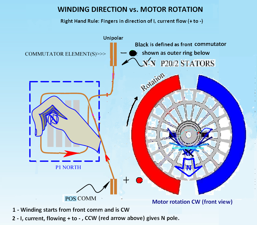
    This is a great reference and text book on which we agreed in another thread. I happened to find it on line for your convenience. I have the 3th edition beside my computer here. See page 3, figure 1.1. It agrees with my interpretation of field polarity with respect to current direction in the coil.

    And later it that book, this figure confirming direction of rotation. Note the text above the figure. It is a generator so the indicated rotation is opposite from a motor.


    Regards,

    bi
    Attached Files

    Leave a comment:


  • DadHav
    replied
    Originally posted by ewizard View Post
    Asymmetric pulse wheel-motor generator on a bicycle :
    https://www.youtube.com/watch?v=l3_xvqR5QxA
    Hello E, I'm not sure who else may comment on your post but there is some merit, in my opinion, about the posted video. It looks like he is using hub motors which I think is really optimal for bikes and other light weight vehicles. secondly it seems he is not claiming over unity but rather a savings in current draw. You know nothing is acceptable without more proof than what the video depicts but it is possible. I have experimented myself with this type motor and experienced a substantial savings of current draw while feeding back generator coil potential from a pulsed circuit. It was just a small motor and circuit test that accidentally showed me it was possible. So there might be something there.

    Leave a comment:


  • DadHav
    replied
    Originally posted by arch chicken View Post
    Hi dadhave.....sorry for delayed answer......bit bussy these days......
    Ill get som vids and fotos together showing what i do with converting bicycles into electric bicycles.....its easy though.....i use the threepoled desighn on a car radiator fan motor......realy strong torque there.....then i mount it onto a plate shaped to fit into frame of said bicycle.....this plate has two brackets fit to take two motorcycle baterys....one on each side......after that its real simple.....take front sprocket and mount it to motor......lengten the chain a bit and fit onto motor......basic motor speed controll and bobs your uncle!

    Ill post some photos showing what i did as soon as i can.......
    Hello Arch, Good luck with your test. Do you have an OEM motor as well as a modified to make a comparison? All you have to do is make your vehicle with the modification go further using the same battery drain as the one with the OEM. Going faster for a short distance might not mean a modification is better.
    Thanks for answering me.

    Leave a comment:


  • Ufopolitics
    replied
    Originally posted by bistander View Post
    To Ufo and all (who might be interested),

    Do a Google search for: coil magnetic polarity using right-hand rule. Hit the image icon. You will see nearly a hundred images agreeing with my take on the right-hand rule and one single image agreeing with Ufo. And that one image is from the Energeticforum, a post by Ufo himself, so it's likely he drew it.

    Regards,

    bi
    Wow!...that means that I am the "one and only" guy who is correct among so many people??!!

    I bet you ask all those people who made those drawings wrong...how many motors have they assembled from scratch or even wound any motor at all...and you would be surprised none of them have ever touched a motor in their life time...except to turn their switches on or off.

    I will repeat what Citfta have on the signature...
    "Just because it is on You Tube doesn't means it is true...
    "

    But instead I will write it with "Google" instead of "You Tube"...and as a matter of fact they are the same exact thing...Google bought out You Tube...

    Bistander, the only thing I do believe blindly -related to Physics Concepts and all this Fields- are completely true, are only on my own experiments.

    So, make the experiment yourself...like Sampojo did:

    Originally posted by sampojo View Post
    Hey Ufo,

    Kinda ground to a halt when I realized I miscalculated my multifilar gauge needs, with 6 coils wrapped. I got the motor together to do a test spin and it went the wrong direction than planned. so I pulled in your post from p265. Just looking at the North pole, it looked like you had the right hand rule wrong. If you look at my post 7952 diagram this page, you can see I reversed it. This is blowing my mind. I pulled out my physics books and studied online and my diagram still seems to agree with the texts, but my motor is still going in the wrong direction and the coils are throwing a South pole not a North pole!!! So your diagram is still king!!
    Take care Bistander


    Ufopolitics
    Last edited by Ufopolitics; 09-17-2016, 06:57 PM.

    Leave a comment:


  • bistander
    replied
    Coil polarity

    To Ufo and all (who might be interested),

    Do a Google search for: coil magnetic polarity using right-hand rule. Hit the image icon. You will see nearly a hundred images agreeing with my take on the right-hand rule and one single image agreeing with Ufo. And that one image is from the Energeticforum, a post by Ufo himself, so it's likely he drew it.

    Regards,

    bi

    Leave a comment:


  • Ufopolitics
    replied
    Originally posted by bistander View Post
    Thanks Ufo. Edit made. I meant my other left.

    But you are incorrect about the right hand rule.

    bi
    Your new edited post:

    Originally posted by bistander View Post
    Hi sam,

    Your diagram of the right hand rule is correct as shown above. However the diagram on the right showing rotation is backwards. With the armature North pointed downward in the stator field pointed to the left*, rotation is CCW.

    bi
    You are still wrong...

    If the North Stator at Right (Blue) is pointing inwards towards Center of Rotor, and the Rotor is producing a down North the rotation is CW.

    North Stator is repulsing (pushing) Rotor North, as Rotor North is also attracted to seek center alignment with Left South(red) Stator.

    Besides this "seen" interactions... there are another one -not seen- taking place in the back of Rotor North (a South), which gets repelled by South Stator and attracted by North Stator.

    About the "Right Hand Rule", related to Magnetic Polarities and current flow...am not going to argue about it with you here...

    If You really are seeking the truth, just do the simple experiment yourself...wind a coil considering that positive would be pointing towards your hand fingers while you wind, not your thumb...then energize the coil and check polarity on that face.

    If you still see it opposite polarity...then you are considering the Geographical pole is the same as the Magnetic Earth Pole on your compass...

    A Compass "N" is just a Magnetic South Seeking Pole...meaning a Compass "N" is a North Pole...and not a South like other billions of people believe...


    Regards


    Ufopolitics
    Last edited by Ufopolitics; 09-17-2016, 04:28 PM.

    Leave a comment:


  • bistander
    replied
    I made a mistake

    Thanks Ufo. Edit made. I meant my other left.

    But you are incorrect about the right hand rule.

    bi

    Leave a comment:


  • Ufopolitics
    replied
    Originally posted by bistander View Post
    Hi sam,

    Your diagram of the right hand rule is correct as shown above.However the diagram on the right showing rotation is backwards. With the armature North pointed downward in the stator field pointed to the right, rotation is CCW.

    bi
    Hello Bistander,

    I believe you are not interpreting the right diagram correctly...

    The two Stator Polarizations (Red=South, Blue=North) are meaning to be pointing Inwards, towards rotor, (we are not reflecting the outwards pointing polarizations, since they do not take any direct role in the motor action) and not like you are understanding "stator field pointing to the right".

    As the image that Sampojo modified from mine on left is NOT correct, related to the flow of currents (from positive to negative) it will generate a South Field that way, pointing out of screen...and not a North (he reversed the voltage polarities) so, on his motor drawing on right was going opposite than he planned because he wound a South instead of a North at rotor. (read his previous post again)

    Regards


    Ufopolitics
    Last edited by Ufopolitics; 09-17-2016, 03:29 PM.

    Leave a comment:


  • bistander
    replied
    Rotation

    Originally posted by sampojo View Post


    Hi sam,

    Your diagram of the right hand rule is correct as shown above. However the diagram on the right showing rotation is backwards. With the armature North pointed downward in the stator field pointed to the left*, rotation is CW.**

    bi

    After 2 edits. It must be that the armature North actually points upwards causing the actual rotation to be CCW.
    Last edited by bistander; 09-17-2016, 05:17 PM. Reason: *was right. Thanks Ufo,**was CCW

    Leave a comment:


  • Ufopolitics
    replied
    Originally posted by sampojo View Post
    Hey Ufo,

    Kinda ground to a halt when I realized I miscalculated my multifilar gauge needs, with 6 coils wrapped. I got the motor together to do a test spin and it went the wrong direction than planned. so I pulled in your post from p265. Just looking at the North pole, it looked like you had the right hand rule wrong. If you look at my post 7952 diagram this page, you can see I reversed it. This is blowing my mind. I pulled out my physics books and studied online and my diagram still seems to agree with the texts, but my motor is still going in the wrong direction and the coils are throwing a South pole not a North pole!!! So your diagram is still king!!
    Hey Sam!

    I am glad you have realized the proper way to obtain the right magnetic polarities.

    Sometimes, -if the structure of motor allows you to- by making either a Full 180º reversal of Stator's Housing, leaving brushes in the same place, this will reverse your rotation. Or the same reversal of rotation could be achieved by just rotating 180º the brushes caps, leaving stators in the same position...just two simple ways to reverse rotation by changing either the static plane or the brush plane.

    Originally posted by sampojo View Post
    Was up till 5AM recently going over a wire recalculation. Looking at a bifilar 24ga wire now. I think it gets me to 21 ga by wire cross-sectional area, but equals the original 19 ga in conductor surface area. My calculations are showing this rotor can't hold enough wire to get to one ohm per coil using a wire that approximates the 19 ga in cross-section area. And I want to get over an ohm, about 1.1 or 1.2. Going to do a test wind on one rotor void area. A fully filled rotor void I have figured will take 270 to 320 strands of 24ga. Also going with a coil that subtends only 10 poles, not 12, with only 6 subcoils each subtending only 5 poles not 6.
    Sorry about that!...now before you keep going, measure your brushes resistance per each vertical -in line- connection, remember brushes are in series related to each coil being energized, so they will add up, and sometimes they will get you over the 1 ohm resistance per interaction, if there is not much difference.


    Kind Regards


    Ufopolitics

    Leave a comment:


  • sampojo
    replied
    Going to try to get my Baldor restarted

    Hey Ufo,

    Kinda ground to a halt when I realized I miscalculated my multifilar gauge needs, with 6 coils wrapped. I got the motor together to do a test spin and it went the wrong direction than planned. so I pulled in your post from p265. Just looking at the North pole, it looked like you had the right hand rule wrong. If you look at my post 7952 diagram this page, you can see I reversed it. This is blowing my mind. I pulled out my physics books and studied online and my diagram still seems to agree with the texts, but my motor is still going in the wrong direction and the coils are throwing a South pole not a North pole!!! So your diagram is still king!!

    Was up till 5AM recently going over a wire recalculation. Looking at a bifilar 24ga wire now. I think it gets me to 21 ga by wire cross-sectional area, but equals the original 19 ga in conductor surface area. My calculations are showing this rotor can't hold enough wire to get to one ohm per coil using a wire that approximates the 19 ga in cross-section area. And I want to get over an ohm, about 1.1 or 1.2. Going to do a test wind on one rotor void area. A fully filled rotor void I have figured will take 270 to 320 strands of 24ga. Also going with a coil that subtends only 10 poles, not 12, with only 6 subcoils each subtending only 5 poles not 6.

    Originally posted by Ufopolitics View Post
    Hello Sam, great to see you as to know you also have some time now!

    That would be an interesting motor when finished, am sure off.

    Now remember that the terms CW or CCW are completely relative and dependent from the reference point you are setting your watch/clock...

    For example take a look at this old diagram when we were winding N-S Pairs, but just focus on the North/Blue side:

    [IMG][/IMG]

    Normally our reference point has always been the side of shaft where we are connecting to take power off, remember?

    [IMG][/IMG]

    Above same image without the hand reference method.

    So let's say you will start from the positive(+)commutator, which, at the same token is where power take off Shaft is, meaning on graphic, the top starting point (1). So the North Pole would be aiming towards screen, and if you set your watch with the clock needles shaft also pointing towards screen, then it would be a CW winding. However, if you set the watch shaft aiming away from screen...then that same winding direc tion would be CCW...see why it is all relative?

    To play safe just do one set of windings first hooked to both comm elements...then power up coils with a small battery source and read outward magnetic orientation on both cores...

    Hope all this free time will allow you to complete the whole thing...it seems you have all the mechanical structure already finished...so it is just winding and connections to commutators, then fire it up...


    Kind regards


    Ufopolitics

    Leave a comment:


  • ewizard
    replied
    Asymmetric pulse wheel-motor generator on a bicycle :
    https://www.youtube.com/watch?v=l3_xvqR5QxA

    Leave a comment:


  • arch chicken
    replied
    Originally posted by DadHav View Post
    Hello Arch, That could be pretty good news. If I understand your statement, you are manufacturing a bike to electric bike conversion and using motors based on the asymmetric designs posted on this thread? If you are doing this there would be a lot of people who would like more information about your motor conversion. If you have something that is tested and an improvement over the standard OEM it would be very kind of you to share some information.
    John
    Hi dadhave.....sorry for delayed answer......bit bussy these days......
    Ill get som vids and fotos together showing what i do with converting bicycles into electric bicycles.....its easy though.....i use the threepoled desighn on a car radiator fan motor......realy strong torque there.....then i mount it onto a plate shaped to fit into frame of said bicycle.....this plate has two brackets fit to take two motorcycle baterys....one on each side......after that its real simple.....take front sprocket and mount it to motor......lengten the chain a bit and fit onto motor......basic motor speed controll and bobs your uncle!

    Ill post some photos showing what i did as soon as i can.......

    Leave a comment:


  • Ufopolitics
    replied
    Originally posted by arch chicken View Post
    Ufo.....
    Thank you for your dedicated focused release of this tech........I am always following in back ground and am astounded by all achieved so far.....
    I have been collecting and compiling all of your threads into pdf format...problem is ....there is no relaese date......Yoy keep on writing new chapters!
    Keep it up!
    Oh...and congrats on the way you are handling this particular thread.........how did you get erfinder to be so plassid!......
    I have replicated all so far....including your timeless motor.......but I have still to do the all north poled desighn......dumbass like me needs a lever to get my head arround the wiring diagram

    The imperial motor has caused me to twice land in hospital from shear exilliration.........build myself a trike from scrap bycicles and power it with said motor.......
    If it wasn't for this particular thread I would have been unemployed and on streets.....what can I say but a heartfelt thank you sir!


    SALUTE COMPADRE!
    My pleasure Arch,

    Very glad you are doing fine!

    When you try the All North...is gonna be even more fun...so make sure you are prepared for it...


    Kind regards friend


    Ufopolitics

    Leave a comment:


  • arch chicken
    replied
    light peace and love to all

    Ufo.....
    Thank you for your dedicated focused release of this tech........I am always following in back ground and am astounded by all achieved so far.....
    I have been collecting and compiling all of your threads into pdf format...problem is ....there is no relaese date......Yoy keep on writing new chapters!
    Keep it up!
    Oh...and congrats on the way you are handling this particular thread.........how did you get erfinder to be so plassid!......
    I have replicated all so far....including your timeless motor.......but I have still to do the all north poled desighn......dumbass like me needs a lever to get my head arround the wiring diagram

    The imperial motor has caused me to twice land in hospital from shear exilliration.........build myself a trike from scrap bycicles and power it with said motor.......
    If it wasn't for this particular thread I would have been unemployed and on streets.....what can I say but a heartfelt thank you sir!


    SALUTE COMPADRE!

    Leave a comment:

Working...
X