 Tweet
Tweet
F & R Switch...
Hello Kogs,
The F & R Switch (or FNR) best choice would be the Club Car type...NOT the EZ GO...Only problem we have is that Symmetric Type Motors have only one Input...we have Four.
Club Car Forward and Reverse Switch 1984 05 DS 36 Volt Resistor Golf Cart | eBay
Rotary Contacts come with a "bridge" type COPPER PLATE like below:
[IMG]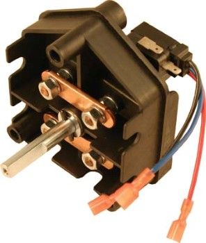 [/IMG]
You must remove it, in order to use ALL FOUR INDEPENDENT CONTACTS.
The Micro Switches are for Reverse Buzzer and to activate Solenoid low voltage coil at Reverse set.
Here is a Diagram of Positions plus Internal Connections (without Bridges)
[IMG]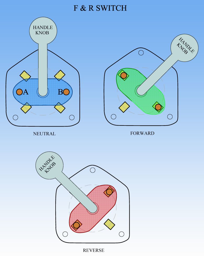 [/IMG]
The Rotary contacts A and B are isolated from each others, they are Copper Bolts like heads with springs for pressure at time of contact...they have thread and nuts to connect cables and they will rotate freely also, within its housing.
The Bridge Plates that you would remove are located at the Steady Plate Four Contacts.So your Total contacts would be SIX(6) Contacts...Two at Rotary side and Four at base plate.
Still figuring out best way to install this switch to Nessie...So...don't buy it yet!!...
Regards
Ufopolitics
Originally posted by iankoglin
View Post
Hello Kogs,
The F & R Switch (or FNR) best choice would be the Club Car type...NOT the EZ GO...Only problem we have is that Symmetric Type Motors have only one Input...we have Four.
Club Car Forward and Reverse Switch 1984 05 DS 36 Volt Resistor Golf Cart | eBay
Rotary Contacts come with a "bridge" type COPPER PLATE like below:
[IMG]
 [/IMG]
You must remove it, in order to use ALL FOUR INDEPENDENT CONTACTS.
The Micro Switches are for Reverse Buzzer and to activate Solenoid low voltage coil at Reverse set.
Here is a Diagram of Positions plus Internal Connections (without Bridges)
[IMG]
 [/IMG]
The Rotary contacts A and B are isolated from each others, they are Copper Bolts like heads with springs for pressure at time of contact...they have thread and nuts to connect cables and they will rotate freely also, within its housing.
The Bridge Plates that you would remove are located at the Steady Plate Four Contacts.So your Total contacts would be SIX(6) Contacts...Two at Rotary side and Four at base plate.
Still figuring out best way to install this switch to Nessie...So...don't buy it yet!!...
Regards
Ufopolitics


 (just kidding there)
Comment