If this is your first visit, be sure to
check out the FAQ by clicking the
link above. You may have to register
before you can post: click the register link above to proceed. To start viewing messages,
select the forum that you want to visit from the selection below.
Well, it's not the rheostat, I already fried that. . So it must be what you call the dialer. The old manual, calls it a reactor. I'm gonna play with it over the next few days, see what I can use it for.
How's it going eh! I managed to get the reactor out of the old welding machine/gen. I'm thinking this might be salvageable. If so, I wonder if I could use it to control my input, to the imperial/alte. You know what I mean. It's got a small wheel, to control the resistance of a lg gage coil. Heavy duty. Needs some work, but I know I can fix it. Any thoughts? I'm gonna start looking for something if this won't do it. I probably only need 150 v@ 30 amps, maybe less, at least to get a good enough set of data. That would be a nice test,
0-150 v, 0-30 amps, or close to that.
Regards
Machine
Hello Machine!
Friend, I honestly do not have an idea of what are U Talking about...seriously...reactor?...Ok, maybe you mean the Dialer or Rheostat for welder amperage output?
I don't know if it will work for those purposes you mentioned...remember that most welders work on low V and High Amps...the other way around could burn resistor, if Watts are not same I suppose...but you have info on welder spec's right?
Still am not sure if that's what you want to do friend...if you could tell me more or if am right...
@UFO
I have another question about using the fiberglass stator. I don't recall this being covered, can I use the fiberglass stator in a generator? I want to try the Spyro of Life winding on a 12 pole to match the motor I am trying to build. Do I pulse the stator at the same time as the motor or is there some other sequence I should use? Should I pulse it faster to match the RMPs of the motor? Just thinking ahead.
Motor Progress: the space on the end of the stator was not big enough to hold the wire so I have to make another one with more space on each end. A few more days to see if it all fits together without rubbing.
How's it going eh! I managed to get the reactor out of the old welding machine/gen. I'm thinking this might be salvageable. If so, I wonder if I could use it to control my input, to the imperial/alte. You know what I mean. It's got a small wheel, to control the resistance of a lg gage coil. Heavy duty. Needs some work, but I know I can fix it. Any thoughts? I'm gonna start looking for something if this won't do it. I probably only need 150 v@ 30 amps, maybe less, at least to get a good enough set of data. That would be a nice test,
0-150 v, 0-30 amps, or close to that.
First Two of the small My Motors I am re winding them as my first rewinds were not balanced and were getting hot. I think that when I measured the Ohms on each armature coil It measured 7 Ohms but I forgot and did not measure the Ohms of the DMM which varied according to the ambient temperature so I measures each coil and they measured 7 ohms and the DMM measured 4 Ohms so in fact each coil was only really 3 Ohms As I was unwinding the motor I found that I had not wound exactly the number of turns on each Pole so I used a counter on the 1000w motor So I am waiting for some finer wire to rewind these 2 motors.
After I rewind these 2 motors I will wind the one Imperial P56 motor 14 winds per half pole using 1mm diam. wire
Second then the tricycle the 1000w ZY Chinese motor It is wound with .6mm diam. wire and 25turns each half pole and so each Pole is 2 x 25 = 50 turns measured with a DMM is 1.4 Ohms minus the DMM=4 Ohms is 1 ohm per pole.
The motor runs smooth and does not get hot nor does the Monster driver it draws unloaded at soft start 2 amps fast star tup 3 amps settling down to 1.2 amps.
G'day UFO and Team
I just finished re-winding the 2 smaller MY motors they were both wound with AWG #23 .56 diam. wire.
The 20 pole I wound 25 S and 25 N per pole.
The 16 pole I wound 31S and 31 N per pole
My DMM Ohms was reading .4 Ohms
All the poles of both motors read with my DMM 1.1 Ohms with the exception of the 16 pole motor the last 2 poles measured 1.2 Ohms
So 1.1 Ohms subtract the .4 Ohms =.7 ohms on each pole Both motors ran cold using 12v,24v and 36v but when running the 24 and mainly the 36v the unbalance of both motors became apparent They need to be Balanced so I will now wind one Imperial and send them all away about 500k to Melbourne to be varnished and Balanced.
When I ran the motors I was using a JS monster and when the last motor the 16 pole was running at 36v the motor at full revs was shaking tooo much and instead of reducing the pot I switched off the battery to the circuit and it seemed to blow out the Pot? I will have to investigate further
Before I can wind the Imperial motors I still need to set the Brush boards to the Drive end and then calculate exactly where the Commutators go then mount the Brush boards and commutators. I will only wind one Imperial first to connect up to my Meccalte Gen Head
I will keep you all updated as I progress
Kindest Regards to you my friends
Kogs still progressing slowly as my Knee is still sore
Ok, I believe you already have clarified this doubts...right?
But anyways I would go over them...
When we have a Two Stator, Two Brush Structure, we try to use advantage of BOTH, Repulse and Attract Modes from just ONE Pair, as shown in your P20 Diagram.
Now, when you reverse coils feed like shown in your last diagram of the same P20...what you are doing is just swapping the repulse-attract Interactions positioning, therefore changing rotation sense. also note the rotor is set in NEUTRAL Position related to the SOUTH Stator Bisector or at perfect TDC.
Please do not confuse when I set the P15 on Attract and Repulse modes before, note that ALL Interactions are FULLY, either repulse or attract for each diagram...Why?...because if you look at them again, closely...would notice that in the Attract Mode...the Repulsion Angles set of Bisectors is so far away that it would NOT Count (disregarded) as it will for the Attract Mode Angles that BOTH BISECTORS create (Stators and Rotor Coils) are very close (shortest angle) and it has become the main "motoring" function here...and so on the opposite with the Repulse Mode.
[IMG][/IMG]
[IMG][/IMG]
Now, You cited Imperial, which is a Four Stator, Four Brush Structure...and related to Repulse Attract we can NOT relate the same way we did with a Two Pole System...take a look:
[IMG][/IMG]
Please note that ALL (MOTOR) Coils, meaning P1-P15, no matter if North or South are all at Repulsion Mode related to each corresponding Stator Bisector, either North or South. P8-P22 are Generator Coils in this Diagram, so, if fed externally, it must be done in the same polarity direction as they output, meaning reversed to Motor Coils.
I don't know if you remember, cause you are not working with Imperial...but we had an issue with swapped magnet stators from factory mount, set differently than my drawing above...creating Machine to work on Attract Mode...even though the guys were doing everything correct,...This caused (because of poor timing related to attract mode) the rotor not to reach desired RPM's as in Repulse Mode, as well as poor Torque.
Let me know if you "Capisci" better now...
Regards
Ufopolitics
Hello Sam
All the Bold-Red Text is my Edit from that post in order to clarify avoiding confusion with Output Coils that look in Diagram as they are at Attraction Mode..but they are not.
@UFO
Thanks for the quick reply. The rotor is completely wound with P1 opposite the comm P1 (180 deg.) I made one of my parts with the brushes at the wrong angle, so I need to remake one part. The information you included was just the right stuff for me to finish. I hope to have it complete next week and I will post some data. The bearings are larger than the comm so I have to press on the bearings when assembled but all is good. Thanks again for the timely information, the video was great.
PS: I am winding the stator now.
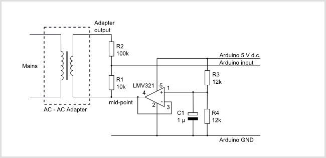
You don't mind if I try to add an ac voltage sensor ...
Hello @Machine, sorry to be little late with the reply. By all means you may make additions. It is open source in our this UFO Thread. Of course always state what the new enhancements are supposed to do and save as the next version and also put your name etc where your additions in a comment line or something. We will get better as we move along.
In this particular version for the dual pentagon motor, the voltmeters are less than perfect. Why? In the next version for this software to be used with the likes of imperial etc, NO GROUNDS WILL BE SHARED BETWEEN THE SENSOR AND THE ARDUINO. Johnstone had talked at length about this in the past. I hope all is well with JS too.
For the Arduino program Development I use Arduino IDE as most people.
For presentation of results I use Processing Program.
In my case, once Arduino is Running a program and it is outputting serial data using commands
Serial.print('H'); // unique header to identify start of message
Serial.print(",");
Serial.print(celcius,0);
Serial.print(",");
Serial.print(fahrenheit,0);
Serial.print(",");
...
and so on
The Processing program just listens to this serial data output. It does not want to know anything else. I have posted at the end of this reply the corresponding processing Sketch.
I had in mind to tidy up the programs when little spare time becomes available
I am willing to answer questions and extend help as best I can if one is needed on the Arduino matters. That includes Zardox, Iankoglin, and all our other friends. Together with UFO we can win all the challenges here.
Here is one example of Processing Sketch
Notice I am NOT running any Arduino IDE.
The only sketch that is running is the processing sketch (as shown on the LCD Monitor).
I am using Ubuntu Linux but that can be windows or Mac too.
This computer is just connected to the experimental Arduino setup.
The Arduino itself is running the arduino-sketch-program
Next coming presentation will be REAL DATA on the Dual Pentagon asymmetric motor.
The weather as of late has not been very cooperative. I hate ICE.
UFO you do not have to worry about icy-rain! I hope where you are.
I better go to bed now.
Warmest regards and Namaste
lightworker1
==============================
This processing program was named:
// Processing Sketch to read comma delimited serial
// expects format: H,degC,degF,volts1,volts2,rpm,
import processing.serial.*;
Serial myPort; // Create object from Serial class
char HEADER = 'H'; // character to identify the start of a message
short LF = 10; // ASCII linefeed
String degC = "";
String degF = "";
String volt1 = "";
String volt2 = "";
String rpm = "";
String TempStatusString ; // Temperature Status has possible values 0, 1, 2
String TempCondition = ""; // This variable just stores one the values: Normal, Abnormal, or Critical Temperature
String AmpsIN = ""; // Amps measured by the ACS712 Low Current Sensor.
float TempStatus ;
PFont myFont; // The display font
PrintWriter output;
// WARNING!
// If necessary change the definition below to the correct port
short portIndex = 0; // select the serial port, 0 is the first port
void setup() {
size(960, 640);
// You'll need to make this font with the Create Font Tool
myFont = loadFont("DejaVuSansMono-Bold-72.vlw");
textFont(myFont, 54);
println(Serial.list());
println(" Connecting to -> " + Serial.list()[portIndex]);
myPort = new Serial(this,Serial.list()[portIndex], 9600);
// Create a new file in the sketch directory
output = createWriter("Data001.csv");
output.println("degC" + "," + "degF" + "," + "volt1" + "," + "volt2" + "," + "rpm" + "," +"TempStatus" + "," +"AmpsIN"); // Write the data to file
// Prefill rectangles and static Header Namese
background(00,00,00);
@UFO
I have a 12 pole rotor and have just finished winding your 12 pole 90 degree brush model. As i stated before I want to use your fiberglass stator method. I understand permanent magnets and replacement electromagnets but your wrap around stator and the brush alignment is not clear in my mind yet. Do you use the same 90 degree offset as the diagram indicates? Can you connect a battery directly to brushes and stator or does it only work if pulsed?
Hello Mike,
The Model I have shown, brushes are set parallel to Stator Bisectors or 90º to Stator Gap Line (I show diagram at the end of video)
Or at 180 (Brushes line parallel to Stator Gap Line)
[IMG][/IMG]
All depends to where you start attaching the first P1 wires to the Commutator Element related to rotor coils and stator bisectors positioning. However, if you have already attached all wires in rotor, just set brushes to 90º, leaving stator at same position as Diagram-video shows.
Related to feeding, it works anyway you want, however, if you used only 1 ohm resistance at stator...it will get very hot at DC straight/linear feed, normally if it is intended to be utilized this way, then much higher resistance should be wound on core, depending on Voltage to be applied.
I built it with lower ohms in order to pulse it and obtain radiant through reverse mode with diodes, just like in my first thread static coils.
It also works on AC low voltage very cool and smooth (I did it feeding it from the secondary of a 24V Charger Transformer, straight AC, not through diode bridge)
I shake my head every time someone tries to mess with this thread and one of (us) your followers responds. I enjoy all of the comments and have been here from post #1 but my results have been so close to others I never felt that posting them would make any difference.
It happens friend, the more successful we are...the more people will enter to mess around...it comes with the territory...
Now, even if your results were very close or even identical to other members replications...It IS very important that you post your results no matter small differences...just one more or less amp, or even Milli Amp could make a difference, besides get Us to establish average data within parameters of feed and outputs.
If they are equal, identical, then we can also run conclusions, then elaborate formulas and calculations, verifying if correct rates remain the same as we increase/decrease feed.
Please remember we are here and as a project gets bigger and more things added (Monster Pulser, Microprocessor, Sensors, etc.) it takes longer to progress. I am still waiting for your full disclosure from the hints you have given over the past 1 1/2 years. We love what you are doing and we hope this year will be your best.
Yes, you are completely right Mike...adding better controllers will do delay progress, for the better though...but still a delay.
@UFO
I have a 12 pole rotor and have just finished winding your 12 pole 90 degree brush model. As i stated before I want to use your fiberglass stator method. I understand permanent magnets and replacement electromagnets but your wrap around stator and the brush alignment is not clear in my mind yet. Do you use the same 90 degree offset as the diagram indicates? Can you connect a battery directly to brushes and stator or does it only work if pulsed?
I shake my head every time someone tries to mess with this thread and one of (us) your followers responds. I enjoy all of the comments and have been here from post #1 but my results have been so close to others I never felt that posting them would make any difference. Please remember we are here and as a project gets bigger and more things added (Monster Pulser, Microprocessor, Sensors, etc.) it takes longer to progress. I am still waiting for your full disclosure from the hints you have given over the past 1 1/2 years. We love what you are doing and we hope this year will be your best.
I just want to say you're awesome!! Very sorry to hear about you're loss of income! I hope you get back on track with everything in your life!
Thanks for the replies to everyone else. I understand how hard this task must be, and it's great that those who are capable are willing to put so much into this.
I've been on the side lines observing and still doing my best to learn and understand. Along with learning more about the general subject. It got me off my lazy a55 to set up a solar panel to power out door lighting, and starting to play around with arduinos to having motion activated indoor lighting too. A small start to my journey of learning about these things. So I just want to thank you for your inspiration and thank you for the excellent contribution you're all making!
Hi Ufo, this is my first post, I have been following these 2 threads from the beginning and watch all your videos. I have a hard time logging to this Forum, because my ISP has been blacklisted or maybe once in 4 months I have root-kits on my computer.
I am on pension. 24/7 on the internet searching for free energy. I have no background on electronics but have been interested from Joule thief. Your disclosure have easily teach me about cold electricity. I am greatly thankful for your simple teaching.
I replicate your asymmetric motor on automobile cooling fan while I was having cataract on one eye. First try was great, runs cool, no sparks, good brush alignment, fast, lots of torque, input 12v, output 36v. Was ecstatic at that time, then try on 24v, was doing very good for a while until the body came apart, because I was using pipe clamps to joint 2 motor frame to one. The motor was spinning too fast for the clamps to hold. By than my second eye got cataract so have to stop winding motors.
Had my eyes operated last month. Starting to build on the automobile fan motor and controller. Have to learn fast because someone is giving a 100HP Generator.
My internet connection is very slow, sorry can't upload vids. I will if I have the chance.
this is now my first post after almost two years here in this excellent Forum and this brilliant thread. I have a very high respect for you UFO and your work and the whole Team participating in this project. I have learned so much in the last two years reading you guys and also doing my own experiments. I have also converted a Mabuchi motor in an asymmetrical way at the very beginning of this thread coming from a Bedini style motor and it worked brilliant until it burned up because of oil at the commutators. Torque and speed were outstanding and unfortunately I was not able to finish all my testings on this Princess. Right now I am back on the Bedini style and still experimenting on reduction of Input Power to the lowest possible. My conclusion so far with my experiments is that this can only be achieved by resonant LC circuits for the firing coils also concerning Vortage differential of the power supply. On the generating side I have also seen pretty good results with shortening techniques. Right time and duration reduced Lenz to a minimum and I feel it can also work positive when correctly done. Also Erfinder has build very nice motors showing this effect. However I feel that all of us in this Community can improve in working together. I also read in the other threads and they are also full of brilliant and useful information. E.G. Turions 3BGS system, Duncans New Year thread, the reactive power thread. I honestly think that bringing all the ideas and knowledge together wenn all could be much more successful and finally solve this topic for the wealth of humanity. Thanks UFO again and the Team and keep up your brilliant work.
Best regards from Germany
Siggi
Many Thanks Siggi and Welcome!
You are completely right, there are many Topics, Threads here of very high interest in order to reach our goals...and of course, it would be great if we all could join forces together...but unfortunately, some are not showing the "whole thing"...and we will never get there like that.
I've been told Erfinder has very good machines...however, he is reluctant to display details...I already have ask him to post it here...but he would have his reasons my friend.
Yes, Duncan's Thread is very good!, excellent material there!!
Also the 3BGS is a very interesting Thread
If You could post in more detail, about your work and results at output shorting or other interesting tested results you've mentioned...that would be a great contribution to our work here, Siggi, I know we all would really appreciate it, as it may "speed things up"...
Stay strong and keep fighting! I've been knocking on doors all over Japan. They are happy to see you but they want a patent! Japan is an OEM country. So they close their doors quickly! But importantly, they all are very interested!
Thanks Midaz, and nope, I will never, ever give up fighting, my Dear Friend...
Yes, I know "OEM" (Original Equipment Manufacturer)...meaning "No Clones" allowed...No "Aftermarket" Permitted...No Black, nor Grey Markets...
Patents...The "only" way to "Protect" your "Intellectual Property"...And that's absolutely right, they do protect ideas, but, in order to be "Sold, Packed, Shipped and Delivered" to a Manufacturing Corporation...Or legally speaking "The Assignee"...Assignee pays big Legal Tender Notes for this Patent...Inventor must forget, like erasing memory in a Science Fiction Movie...that he ever invented such great Machine...or Product...If He Violates "Codes of Assignment Transaction"...He will get penalized under the ISA (Inventor Secrecy Act) 1953...Federal Jail Time plus very High Fees...etc,etc
So, yes, you sold this...no one else could massively produce this product ever...basically, if an Oil Cartel Corp bought it...Now, even a dedicated manufacturer corp for that particular patented invention(like this company you went to)...sees that there would be future threat IF manufactured, to either National Security or Other Related Interests...then, very intelligently...they will "re-sell" whole package to the Evil itself for "Properly Disposal" of such "Dangerous and Heretic Material"...Capisci?
I know most workers do not know about this way to "handle" packages...so, we can not blame the Old Man you went to see...it is absolutely not his fault.
I went to the largest and most famous electric motor company in Japan. I rode a 50cc scooter for 2hrs one way to meet them in the freezing cold! The head engineer is over 70. He's the man! He has been doing electric motor work for over 50 yrs! Everyone was happy to see me but the expression on his face and body gestures were like, "I've seen everything. Hurry up, your wasting my time!" I opened the motor up 24in in front of his face because his opinion was the only one that mattered!... After looking at the motor winding and comms carefully. He took his glasses off and said, "What is this." Before I could explain all. He stop me before I could finish and said, "This motor should be very fast." I said "Yes". He understood the windings and comms! At that point the VP asked for the patent.... To make a long story short. The old man walked me out to my 50cc scooter in the freezing cold. He said his company will not help but I have a good motor!.. I don't think that he has smiled or has had a machine that has truly caught his attention in a looooog time! He sent me some free parts.
UFO, I know you like to help everyone but stop wasting your precious time making cads, wire designs and answering questions for people that have not taking the time to watch all the vids, let alone read the two threads. Give yourself some time to relax and regroup.
Dana's motor will have a DYNO, stress test, balanced and see if it will be cost effective to mass produce. The results should take a few weeks.... Until report card day, everyone be patient, keep building, testing, studying and innovating.
Keep it Clean and Green
Midaz
Thanks Midaz for this excellent Post!, Also, thanks for all your effort to help on this...but I will NEVER be Patenting this Methodology...not for all the legal tender notes out there...not even if I have to go and live under a bridge with my friends the Homeless Veterans of War Consequences from this country...
Helping others is my job Midaz, like I helped you build your Imperial patiently, explained errors...fixed timing alignments, etc ...if they do completion or don't, that's their problem, not mine, they will "miss it"...but, anyways, I know what you mean, and thanks friend.
That old man smiled...just because he knew what you had in your hands......He only wished you would have had a patent on it, in order to take it into "further steps"...but their own "Protecting System" Denied Access to proceed... ...And I love that!......just like a boomerang...and I hope you understand me...even if I sound like "not making sense" why being happy when they did not bought our Imperial...
Leave a comment: