Announcement

Collapse
No announcement yet.

Isolation Amplifier

Collapse
X
 
  • Filter
  • Time
  • Show
Clear All
new posts

  • Isolation Amplifier

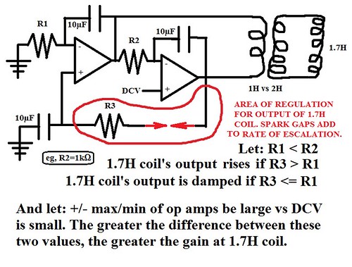
    High voltage operational amplifier is nothing new. Negative resistance is nothing new. While toying with a simulation of a 'sine wave generator' plus a load attached to it, I discovered that I can regulate the output up or down - overunity vs damping - by adjusting one resistor. And by adding one or more spark gaps of extremely low breakdown of resistance to voltage, I can maintain the smooth sine wave output at the load, accelerate the rise towards infinity, and reduce the voltage to amperage ratio so that the high voltage doesn't dominate the amperage too much -- at least while the spark gaps are engaged. I can only engage them momentarily since the escalation is too drastic to maintain for very long.

    I use Paul Falstad's simulator. Despite all of the criticisms for simulating anything instead of doing it, or using his simulator in particular, I find it instructive to learn basic principles without much fuss, expense or risk of electrocution since I have no formal training with any of this.

    The attached file should work at either of these three locations which host Paul's simulator...

    Circuit Simulator Applet - originating author written in Java

    Circuit Simulator - contributed portage to JavaScript

    Circuit Simulator Applet with my mods [circuit loads immediately]
    Attached Files
    Last edited by Vinyasi; 07-19-2017, 06:00 AM.

  • #2
    How much do you know about op amps normally?

    The ratio between the feedback resistance Rf and the gain resistance Rg determines the gain A.K.A. amount of amplification. The labelled + and - refer to inverting and non-inverting signal inputs, not power supply.

    Your op amp supply voltage is set as +/- 1 GV = 2 billion volts rail to rail. Good luck with that!

    https://www.allaboutcircuits.com/tex...tive-feedback/

    https://www.allaboutcircuits.com/tex...tive-feedback/
    Last edited by dR-Green; 07-19-2017, 02:56 PM.
    http://www.teslascientific.com/

    "Knowledge is cosmic. It does not evolve or unfold in man. Man unfolds to an awareness of it. He gradually discovers it." - Walter Russell

    "Once men died for Truth, but now Truth dies at the hands of men." - Manly P. Hall

    Comment


    • #3
      Teensy disappointment

      Originally posted by dR-Green View Post
      The labelled + and - refer to inverting and non-inverting signal inputs, not power supply.
      I wondered what those editable settings referred to. And I wondered why there were no cross arms drawn onto each op amp image.

      It figures that a high supply voltage would 'lead' or 'tease' the output to reach for infinity if the supply voltage was excessively greater than the signal voltage.


      At least I got something out of this study: that the bottom-most resistor can greatly affect the outcome: damping vs escalation of output when its value is set to be less than or equal to the upper-left resistor vs greater than, respectively. Neon bulbs also help to accelerate the rise of output.


      Since the simulator would always crash well before the output reached the same level as the supply voltage, no overunity to report here. Shucks.


      Thanks for the heads up.
      Last edited by Vinyasi; 07-20-2017, 02:43 PM.

      Comment


      • #4
        This is a typical non-inverting op amp circuit:

        http://tinyurl.com/y9z3lnab

        As you can see, the gain or output voltage is controlled by the ratio between Rg and Rf because that's what determines the amount of feedback, and the op amp amplifies the signal depending on the difference between the + and - inputs via the feedback. If you remove the feedback network then the gain will be infinite and the output will go up to the supply voltage.

        https://electronics.stackexchange.co...p-amp-circuits

        https://www.khanacademy.org/science/...nverting-opamp

        https://www.khanacademy.org/science/...nverting-opamp
        http://www.teslascientific.com/

        "Knowledge is cosmic. It does not evolve or unfold in man. Man unfolds to an awareness of it. He gradually discovers it." - Walter Russell

        "Once men died for Truth, but now Truth dies at the hands of men." - Manly P. Hall

        Comment


        • #5
          Originally posted by dR-Green View Post
          This is a typical non-inverting op amp circuit:

          http://tinyurl.com/y9z3lnab

          As you can see, the gain or output voltage is controlled by the ratio between Rg and Rf because that's what determines the amount of feedback, and the op amp amplifies the signal depending on the difference between the + and - inputs via the feedback. If you remove the feedback network then the gain will be infinite and the output will go up to the supply voltage.
          This is very helpful since it points out that overunity, if possible, could not be a direct consequence of the op amp. But it could be an indirect consequence if the supply voltage is relatively cost free.

          Meaning, whatever supplies the voltage for the op amp, that device, not the op amp, will determine the overunity.

          The advantage of bothering to attach an op amp onto an already existent overunity device would be if that device supplying the op amp's voltage had a messy output and the hope is to clean it up - at least somewhat - to become a nice sine wave with the help of the op amp acting as a filter, or modifier.

          Thanks.

          Comment


          • #6
            The First Step of Creating a Cost-Efficient Op Amp Power Supply ....

            .... is to create from scratch my own pair of op amps (supplying a load) with the intention of eventually attaching a self-running power supply to this pair of op amps to bring the cost down to a negligible value of almost nothing.
            Attached Files
            Last edited by Vinyasi; 07-23-2017, 03:05 AM.

            Comment


            • #7
              Originally posted by dR-Green View Post
              If you remove the feedback network then the gain will be infinite and the output will go up to the supply voltage.
              I thought I included feedback in all of my op amp experiments?

              Comment


              • #8
                Infinite Output from One Volt AC Powering an Op Amp Sine Wave Generator

                My rejected edit at stackexchange ...

                "The output of the opamp (and to some extents the input also) is constrained by the design parameters of the circuit surrounding the opamp including the power supply. For we can sometimes get out more than what the supply puts in under conditions of 'time dependent potential energy' wherein time shifts are variant." - Conservation of Energy is Dependent on Time Frame Remaining Constant

                For example, consider this circuit ...


                BTW, I built these two op amps using this reference and did a short video.
                Attached Files
                Last edited by Vinyasi; 07-23-2017, 07:00 PM.

                Comment

                Working...
                X