 Tweet
Tweet

Uploaded with ImageShack.us

Uploaded with ImageShack.us

Uploaded with ImageShack.us
Hi folks, just wondering if anyone has tried these circuits.
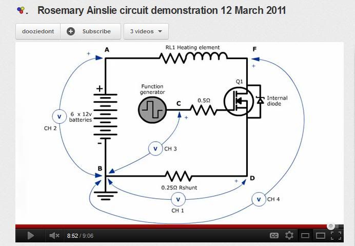
The circuits come from Patricks pdf, panaceauniversity.org/Ainslie_heater_circuit_by_Patrick_Kelly.pdf
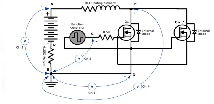
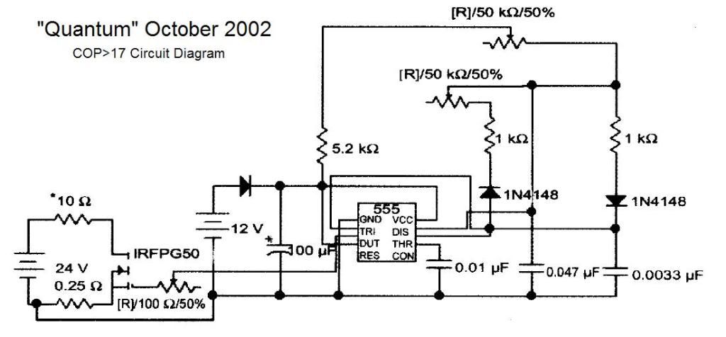
and the other circuit is based more on anslies circuit, though i think it may have an error, since the way Patrick shows it, the flyback has nowhere to go, so i made an edited one to show how to allow the flyback to properly charge the battery, though the original circuit may work, it has been awhile since testing the anslie circuit with 555 timer.
Apparently, the gate resistor to a fet is what causes the feedback or higher than normal oscillations in the circuit and causes high efficiency and possible self charging.
Let me know if you've tried this circuit or would like to, I am going to test these variations.
peace love light
tyson

edit: changed pdf link, was the wrong one.


 ??
??
Comment